Actually the op amp or a Zener diode is more likely to be the problem, even though
the capacitors are old. Could even be a bad solder joint from thermal cycling.
the capacitors are old. Could even be a bad solder joint from thermal cycling.
Replacing parts comes only after a tentative diagnosis. First, check each section of the supply
in turn, starting with the voltage on the Zener string, which should be 394VDC.
Next, check the output of the 12BH7A cathode follower, which should be 402VDC.
The symptoms that you observe are caused by the failure of the power supply to properly regulate.
The audio circuit is oscillating at a subsonic frequency (motorboating) because of this.
The large capacitors may or may not be related to this problem.
“Zener string” - is that the zd 1 through 8?
Actually the op amp or a Zener diode is more likely to be the problem, even though
the capacitors are old. Could even be a bad solder joint from thermal cycling.
Could be. I see I’m in for a pretty big project. This unit was tortured by some “modifier”, phono was totally screwed-up. When I first got it it was exhibiting this motorboating thing, then all of a sudden it started to work normally. Sounded rather bad but worked. Thank I returned the phono to stock, didn’t use it for at least a month, and now it’s oscillating again. I will eliminate the usual suspects first, and will measure the PS. I mean those 12BH7 tubes are notorious for failure in it… But you are probably correct, it’s something like an op-amp, a zener or a cold solder joint. Thank you for your help that came so soon!
Right, measure the voltage at either pin 2 or 7 of the 12BH7A grids.
The meter ground lead connects to the chassis.
This is the reference voltage for the regulator, and must be correct for it to work.
If the problem was intermittent at some point, this indicates a bad connection as most likely.
Look over all the power supply board connections carefully, especially ones that get hot,
like on the Zeners, tubes, etc. Could even be an oxidized tube socket pin connection, clean them.
Last edited:
Thank you Rayma
I can not get to preamp for a few days, I’m not disappearing. Will check in in a few days.
I can not get to preamp for a few days, I’m not disappearing. Will check in in a few days.
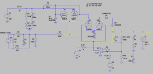
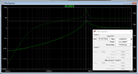
I have a later model SP Preamplifier -- the HV transformer windings burned out, I took the schematic from posted #1 and ran an impedance analysis. "Q" is equal to Group Delay * Frequency * PI = 1.62u * 788kHz * PI = 4.0, and Phase Margin is approximately 14.3 degrees.
Just a simulation, haven't done it on the bench:
Just a simulation, haven't done it on the bench:
Attachments
Hi. Thx. So what does it mean? I’m afraid my knowledge doesn’t go as far as you gurus possess here 🙂). SP-8 has only one transformer for everything; I think if the HV winding has burned out, I wouldn’t get any HV voltage at all. But what I see is that it’s trying to get there, but at about 120 c it drops down to 20. As Rayma pointed out, this is a classic “motorboating” behavior. Problem with regulation rather than transformer supply, I tend to agree. I don’t have time right now to dig into it, but in a few days…
Hi. Thx. So what does it mean?
(Mine is an SP-11)
It means that there's a design flaw. I don't know if anyone was testing phono preamps out to 10MHz in 1982...you could have strong signal from an AM station excite the control loop...
Playing around with some numbers new new C1 (C18 on SP schematic) = 22uF 450V alum electrolytic with some ESR, C34 100pF polypro, certainly not polystyrene. R68 (R4) 0.47 Ohm.
Oh yes, Audio Research was famous for getting all kinds of noises and oscillations. They were adding small caps all the time to try to stop RF and other crap. In fact, this very thread was started because 12BH7 didn’t have enough balls to handle its assignment.
If it's a series pass element, it depends on the plate to cathode voltage drop. If that's not too large, and the current consumption is not too high, the tube could work reliably there. I can't make out the plate voltage form the diagram.
The schematic posted #1 is a later version. Another schematic from 1981 uses an LM741 driving the shunt regulator (instead of TL071) AND, importantly, C17 is not omitted and referenced as 200uF.
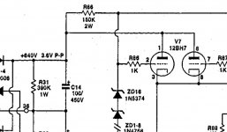
The schematic posted #1 is a later version. Another schematic from 1981 uses an LM741 driving the shunt regulator (instead of TL071) AND, importantly, C17 is not omitted and referenced as 200uF.
I have a schematic revision 7, which was supposed to be the latest one. I’m trying to figure out how to post it. Large caps are 100uf/450v on it rather than 200uf/450v
You don't need a lot of capacitance on the output of the regulator, a bit more than to keep it stable.
If you want a neat solution with minimal real estate consumption and virtually no heat, try Neurochrome's "21st Century Maida Regulator" == stable, extremely quiet, very low impedance:
21st Century Maida Regulator: A modern B+ voltage regulator – Neurochrome
Tom is a regular DIYAUDIO contributor.
21st Century Maida Regulator: A modern B+ voltage regulator – Neurochrome
Tom is a regular DIYAUDIO contributor.
Actually the op amp or a Zener diode is more likely to be the problem, even though
the capacitors are old. Could even be a bad solder joint from thermal cycling.
Hi. I’m back to testing this thing. I feel like giving up. I can’t even bring it up to 70v on my variac and dc swing on output is over 10v…
It's normal and expected to have low frequency oscillation in the audio circuit, when the HV supply regulator
is not working. When the HV regulator is fixed, the oscillation will go away, so ignore the oscillation for now.
Check visually all the solder joints in the HV supply, and look for damaged parts. Check all semiconductors
with the diode function of of a DVM. Post some clear photos of the board.
is not working. When the HV regulator is fixed, the oscillation will go away, so ignore the oscillation for now.
Check visually all the solder joints in the HV supply, and look for damaged parts. Check all semiconductors
with the diode function of of a DVM. Post some clear photos of the board.
Last edited:
- Home
- Amplifiers
- Power Supplies
- ARC SP8 tube reg rebuild