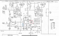
Hi All, happy new year. there attached the ARC sp10 circuit, the red circle is J175 , can i replace it with LM335 .
however i dont know actually this circuit require how much constant current and the LM335 40v can support to this design ? If LM335 is not suitable, can anyone advise other FET and how to set required constant current for this design ?
however i dont know actually this circuit require how much constant current and the LM335 40v can support to this design ? If LM335 is not suitable, can anyone advise other FET and how to set required constant current for this design ?
Attachments
Why do you wish to replace it? Just for fun?
It may depend on your goal to select a replacement.
Jan
It may depend on your goal to select a replacement.
Jan
Of course you plan to diy it.i plan to diy it :> however i can t find this parts
But that wasn't the question.
How can we advise you if we don't know what you want to accomplish?
Jan
J175 is a P-channel JFET (see https://nl.mouser.com/datasheet/2/308/1/J175_D-2314525.pdf ). Does anyone understand what it is supposed to do in this circuit? It acts as a current source with a current that can be anything from 7 mA to 60 mA when the grid is very positive with respect to the cathode of V11 and as a clamping diode when the grid is negative. Why is that desired?
Mouser still has them, both the original J175 and its SMD variant https://nl.mouser.com/c/?q=J175
Mouser still has them, both the original J175 and its SMD variant https://nl.mouser.com/c/?q=J175
The two triodes are wired in parallel.
That fet is acting as a diode to prevent high positive voltage on the grid(s) when the tube is still cold (no current)
Make your live easy, put in a 1N4148 with the cathode on the tube cathode.
Mona
That fet is acting as a diode to prevent high positive voltage on the grid(s) when the tube is still cold (no current)
Make your live easy, put in a 1N4148 with the cathode on the tube cathode.
Mona

It's a P-channel JFET, so the gate-drain diode goes in forward conduction when the grid is negative with respect to the cathode. With the grid positive, it's a current source.
Jan, I think the anodes of the valve are connected, because arcs are drawn wherever things are not supposed to be connected.
Jan, I think the anodes of the valve are connected, because arcs are drawn wherever things are not supposed to be connected.
thx all your input….
Hi MarcelvdG , should i replace it with any P channel mosfet and how much of constant current required ? Not sure LM335 in max 10mA CCS with max 40V can be y
used ? or else just replace with single diode ?
Hi MarcelvdG , should i replace it with any P channel mosfet and how much of constant current required ? Not sure LM335 in max 10mA CCS with max 40V can be y
used ? or else just replace with single diode ?
Sorry Jan i only have this circuit diagram . In fact i bought this pcb but couldnt find this parts , then only search for an alternative ways ☺️
thx all your input….
Hi MarcelvdG , should i replace it with any P channel mosfet and how much of constant current required ?
I wouldn't do that, as a P channel MOSFET behaves very different from a P channel JFET.
Not sure LM335 in max 10mA CCS with max 40V can be y
used ? or else just replace with single diode ?
There are two possibilities:
1. The designer made some stupid mistake and actually expected the J175 to act as a diode that does what Ketje wrote. If that's the case, then you could replace it with a diode.
2. The designer had some very good reason for using a JFET, but none of us understand what that reason was. In this case, you can't replace it with a diode. You could then use a J175 (they are available at Mouser), or its SMD version MMBFJ175, or an N-channel JFET with (except for the polarity) about the same pinch-off voltage and IDSS as the J175 when you swap the drain and source, the gate still has to be connected to the source.
I haven't a clue if the LM335 could be used in case 2.
3. The circuit diagram has an error.
To the OP: de-solder the part, clean it, and carefully resolder it. It the probably sounds much better.
Jan
PS Just pulling your leg. happy New Year.
To the OP: de-solder the part, clean it, and carefully resolder it. It the probably sounds much better.
Jan
PS Just pulling your leg. happy New Year.
@rayma So your hypothesis is that the circuit diagram is indeed incorrect, like @jan.didden suggested, and that the JFET was supposed to be connected as a diode, the diode doing precisely what @Ketje wrote? Makes sense.
- Home
- Amplifiers
- Tubes / Valves
- ARC SP10 replace (J175)