
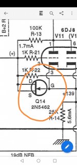
Hi Mar & Rayma you are right , ii double check the PCB , both D and S pins are shorted and connected to grid resistor 1K , then the G is connected to the cathode of the tube
The draftsman was likely not an electronics guy. It was an easy mistake to make for him.
Conclusion of this design of 2N5462 could be replaced by 1N4148 ? If i prefer the sound better, then i can use J175 because i can't find the 2N5462 ?
OK, so now the J175 P-channel JFET changed into a 2SJ175 P-channel enhancement MOSFET... https://pdf1.alldatasheet.com/datasheet-pdf/view/87043/HITACHI/2SJ175.html
OK, then it must be a J175, definitely not a 2SJ175, and it is hooked up as a diode clamping positive grid voltages.Hi Mar & Rayma you are right , ii double check the PCB , both D and S pins are shorted and connected to grid resistor 1K , then the G is connected to the cathode of the tube
That one makes sense, although it also has a drafting error: the P-channel JFET is drawn as if it were an N-channel JFET.That is a different version from the SP-10 line stage schematic that I have. Appears to be a drafting mistake.
In this one attached, the diode is properly connected.
Those all should work just fine, but a 2SJ175 would not work.Conclusion of this design of 2N5462 could be replaced by 1N4148 ? If i prefer the sound better, then i can use J175 because i can't find the 2N5462 ?
You can also use an NFET, just connect the source+drain to the cathode.
But I don't see the use of an ultra low leaking device here. First it's driven by a source at 1,7mA and second the other side of the diode is connected to the output of a cathode follower and so is bootsstapped making it looks like a very high resistance.
An old tric to prevent high voltage on the grid at start-up is a NE-2 neon tube, no leaking at all.
Mona
Does anyone have a comment on ARC's reasoning for using a JFET here (as a diode)? Does it behave better somehow in the negative 0-2 VDC range, compared to the simpler PN junction diode? At first blush, it doesn't look like it would matter all that much?
All good fortune,
Chris
All good fortune,
Chris
I haven't a clue. Some JFETs have pretty good leakage current specifications when used as a diode, but that can't be an issue here anyway.
Yes, almost all uses I have seen were because the designer wanted low reverse leakage.
Maybe this designer also thought it would be an issue here.
Jan
Maybe this designer also thought it would be an issue here.
Jan
Be very careful with the Chinese-sourced PCBs for "ARC" preamplifiers. From what I have seen before, they tend to be simplified versions of the originals, and the relationship between the circuits and the ARC originals is approximate at best. Don't presume that there is any kind of exact correspondence between either the circuit or the specified parts between one and the other. From what I remember of the Chinese SP-10 in particular the power supply and regulators are much, simplifier than Bill Z Johnson's original.Sorry Jan i only have this circuit diagram . In fact i bought this pcb but couldnt find this parts , then only search for an alternative ways ☺️
Alex
- Home
- Amplifiers
- Tubes / Valves
- ARC SP10 replace (J175)