You may have run into power supply limitations.Thanks for the reply. I am planning to revert to the original mute circuit to see if it operates correctly, and if so I will probably do the dead bug style mod to get a signal relay working. I'll probably preserve the existing design (signal going through relay) just to keep it simple for now.
Before I disassembled the 'factory upgrade' circuit I did some measurements of coil voltages to see if I could find out why it wasn't operating with the J2 jumper ribbon connected. With J2 disconnected, the coil voltage was 27.7V unmuted and 17.2 muted. With J2 connected, the coil voltage was 23.3V unmuted and 14.6V muted. I believe this had to do with the slight voltage drop (200mV) on the +16V rail when J2 is connected and is powering devices on the switch assembly board. But even so, the circuit wasn't performing well if it was only able to change the coil voltage slightly between mute/unmute states. I would have expected something closer to the ideal +24V/0V for the unmuted/muted coil voltages.
While the OPA2134 is a great opamp, it draws 2.8 times the current as the TL072 (8mA vs 2.8mA).
The power supply was designed for the TL072, but with the added draw from the mute circuit +18 and +16 feeds, it may be pushed too hard (the original mute circuit does not draw from the regulated supplies). Voltage sag at the relay coil is tell-tale.
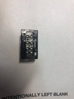
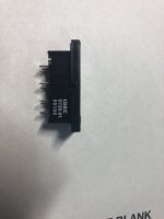
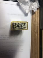
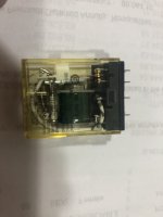
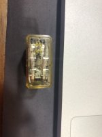
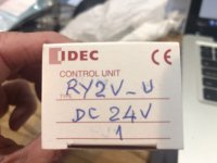
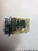
Re. the relay: While the original PCB pin IDEC RY2V-U-DC24 is pretty much unobtanium, the solder-lug version (IDEC RY2S-U-DC24) can still be found, and with judicious use of side-cutters/file/dremel etc, can be modified to drop right in to the PCB holes.
From this:
To this:
Last edited:

@seanc
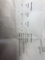
I actually ordered one of those last night from Galco, but it seems like the one I bought is actually the PCB version:
https://www.galco.com/ry2v-u-dc24-idec.html

We'll see when it shows up! I also bought another signal relay to try when I was putting together a Mouser order for the components to revert it back to the original muting circuit.
That's a good observation about the new op amps. I installed DIP sockets everywhere so it will be possible to put the old op amps back if needed and/or for comparison.
BTW I think I got the idea for the Samtec ribbon cables from one of your posts, so thanks! It would have been really difficult to troubleshoot this muting problem if the boards were all permanently connected.
I actually ordered one of those last night from Galco, but it seems like the one I bought is actually the PCB version:
https://www.galco.com/ry2v-u-dc24-idec.html
We'll see when it shows up! I also bought another signal relay to try when I was putting together a Mouser order for the components to revert it back to the original muting circuit.
That's a good observation about the new op amps. I installed DIP sockets everywhere so it will be possible to put the old op amps back if needed and/or for comparison.
BTW I think I got the idea for the Samtec ribbon cables from one of your posts, so thanks! It would have been really difficult to troubleshoot this muting problem if the boards were all permanently connected.
PS. beware there are inconsistencies between schematic & PCB references
Schematic says R90 is 820ohm, PCB says 1K. Schematic is correct.
Schematic says C69 is 1uF, PCB says 0.1uF. PCB is correct.
2SC1345 transistor is unobtanium. KSC1845 is best substitute, but 2n5550 and BC547C will work as well.
2n5087 is still available, 2n3906 will work as well.
Schematic says R90 is 820ohm, PCB says 1K. Schematic is correct.
Schematic says C69 is 1uF, PCB says 0.1uF. PCB is correct.
2SC1345 transistor is unobtanium. KSC1845 is best substitute, but 2n5550 and BC547C will work as well.
2n5087 is still available, 2n3906 will work as well.
Sean's comment is supported by my own experience. I swapped all of my op amps in one of my 3 preamps and the transformer failed. Current draw was too great for the later design, apparently lower VA transformer. I replaced it with a somewhat larger VA Hammond. The greater current draw required a very slightly higher rated fuse as well.
Good find!I actually ordered one of those last night from Galco, but it seems like the one I bought is actually the PCB version:
My relay still works fine, figured if I had to replace it at some point, the solder-lug version mod would work.
The power supply issue has been noted by others, depending on vintage and which transformer was installed. I used OPA1642 (an "improved" 2134) which only draw 3.6mA nom. and 4.6 max (less than TL072 max). SOIC only though.
Yes that was me. The original cables are terrible.BTW I think I got the idea for the Samtec ribbon cables from one of your posts, so thanks! It would have been really difficult to troubleshoot this muting problem if the boards were all permanently connected.
Suggestion: pull all the opamps from the tone/switch board and plug it in.
Does the relay work? If so, likely power supply issue, if not, tone/switch board issue.
Fortunately I still have close up photos of another (early) Apt Holman that I rebuilt last year. It actually had a 1K resistor for R90. I bought both just in case. I have KSC1845s from my Sansui AU-717 projects, and I put a 2N5087 in my order.
If the new relay and reverting to the original circuit doesn't work I will definitely experiment with pulling the OPA2134s. If they turn out to be the cause I'll either go back to the old opamps or try a new transformer. Probably the latter because the new opamps were pricey and it would be a shame to not use them.
If the new relay and reverting to the original circuit doesn't work I will definitely experiment with pulling the OPA2134s. If they turn out to be the cause I'll either go back to the old opamps or try a new transformer. Probably the latter because the new opamps were pricey and it would be a shame to not use them.
Last edited:
I'm reading your thread over on AK at the moment!Sean's comment is supported by my own experience. I swapped all of my op amps in one of my 3 preamps and the transformer failed. Current draw was too great for the later design, apparently lower VA transformer. I replaced it with a somewhat larger VA Hammond. The greater current draw required a very slightly higher rated fuse as well.
All who have replied. I have not completed the "return to factory change". My unit has the original rack mount front panel. I was able to loosen the screw on the top and spray some deoxit into the contact area and have not had a problem since. I have attached the replacement relay from Galco in the US. I paid about $15 for the relay and $2 to 4$ for the socket. If I was to upgrade this I was going to use the socket. In my view this was a complete hack job by apt in the 80's to solve the relay issue. I do like the Jean Paul solution, but for my purposes I want a stock solution. The parts to rebuild the original circuit passive components was about $12 from mouser. Rayma, any member, recommended 2n4403 and 2n4401 as replacement NPN/PNP transistors. I had a price of $30 plus shipping to replace the mute circuit and all the electrolytic caps. I specified all capacitors as Panasonic FR series. They have high ripple and low esr. I used them in my Hafler dh110. I am older and shakier so repairing items like this with a soldering iron is always risky for me. Anyway, I like the sound and features of this preamp. Please reach out if there is anything I can help with.
Attachments
-
 APT Relay 11.JPG224.9 KB · Views: 89
 -
 APT Relay 10.JPG251.7 KB · Views: 94
 -
 APT Relay 9.JPG188.5 KB · Views: 94
 -
 APT Relay 8.JPG168.8 KB · Views: 90
 -
 APT Relay 7.JPG213.9 KB · Views: 101
 -
 APT Relay 6.JPG197.4 KB · Views: 107
 -
 APT Relay 5.JPG149.7 KB · Views: 105
 -
 APT Relay 4.JPG371.9 KB · Views: 100
 -
 APT Relay 3.JPG227.1 KB · Views: 97
 -
 APT Relay 2.JPG300.3 KB · Views: 101
 -
 APT Relay 1.JPG214.2 KB · Views: 100
@Marksd, it's going to depend on how successful the relay fix is. 🙂
I believe people are right that the new op amps are causing the voltage to sag. But I am hoping that the new relay from Galco along with the reversion to the original circuit will get it going again. I should get parts by the end of this week. It will certainly look better inside! If that doesn't work out I am either going to put the old op amps back (in the DIP sockets), or put in a new transformer as GKTAUDIO suggested.
But seriously, about the sale price -- I was contacted by a local buyer who is very interested. I am thinking $750 assuming the mute issue is solved. It's in excellent cosmetic condition, and working perfectly with the exception of the mute circuit.
That may be, however, it is exactly what the factory used. I agree that your signal relay out of the signal path idea is probably better. But I also believe there's a reason the preamp is so well regarded, and that the designer(s) were certainly talented. So in my opinion, going back to the original design is ok as long as it works. If someone else wants to modify it down the road, they certainly can.Marksd, that is exactly the wrong type of relay for the purpose.
Yes shorting outputs to GND functions way better as do sealed relays meant for signal. The factories talented people simply made a few wrong choices in this well regarded but malfunctioning device as explained. One could take a peek at Japanese designs who do this flawlessly for decades already without crackling or relays malfunctioning.
Copying errors exactly is a choice. If the few extra mA of the OPA2134 are an issue maybe a power hungry relay is not the best choice either.
Copying errors exactly is a choice. If the few extra mA of the OPA2134 are an issue maybe a power hungry relay is not the best choice either.
Last edited:
Apt was know to "tweak" the circuit over time (witness the relay circuit).All, please see the mute circuit page of the service manual. Both of mine have a 1/2 watt 1k resistor in the relay drive.
The schematic clearly shows "820", but note the numerals are much larger than the rest of the schematic, which would seem to indicate it was changed from original drawing.
My unit had 820 installed. Might not make much difference, but there it is.
I wouldn't waste money on hi-end caps and resistors. The delay circuit is divorced from the signal circuits, it's only there to trip the relay after a short delay.
There are a couple of other discrepancies between schematic & PCB.
The tone/switch board has two 1meg resistors located between the "Ext processor" and "L>R" switches, not shown on the schematic.
The RIAA stage final series output resistors (R20/R120) are listed as "3K0" (an odd designation), my unit has 2.7k installed
@seanc
I have spare caps from previous projects that I'll use. I even have a 0.1uF cap that's identical to what was there originally that came out of my Sansui AU-717 tone board, so it'll be repurposed here. I agree there's no need for good caps for muting relays, LED resistors, etc. 🙂
Oh, and about the 1k vs 820 -- I saw that the PCB doesn't match the schematic. The other Apt Holman I already overhauled and sold had the original mute circuit and had a 1k. I bought both 1k and 820 just in case the switch to 820 was intended to improve the circuit reliability.
Fingers crossed I won't need to upgrade the transformer or put all the old op amps back in to get it working.
Last edited:
Jean Paul, Thank you for the comment, but my 2nd APT is original and as Booja30 says it is the exact really APT used in the original design. What I will never understand, and this is all second guessing on a 1980 design, is why the 555 wasn't used to trigger the relay. Regardless, that is why I bought a socket in case I have to replace the relay again. Like I mentioned the relay unit after the deoxit treatment has been flawless. I am clearly an amateur and can do basic things for repair. And as I have aged have gotten "more careful". Can someone tell me where the capacitors were installed to protect the FET from static electricity? This was another fix on my original unit. Thanks to all on this thread.
Last edited:
- Home
- Source & Line
- Analog Line Level
- APT Holman Preamps and relay repair