Hi I was reading kenwood classic power amp l-05,7,8, achematic and found that their amplifier design was divided by two stage. First bit was all class A then they add a class b amp stage (sepp circuit) before the end of output.
I was wondering why dont they just make a class AB.
What was the reason adding class B to distort sound.
I was wondering why dont they just make a class AB.
What was the reason adding class B to distort sound.
> First bit was all class A then they add a class b amp stage
Must be some confusion. Maybe model. Maybe terminology. Would help to say where you "was reading".
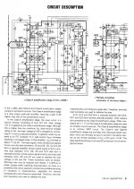
The L-07M seems to be a dead-classic "Class AB" power amplifier. See image.
As always, the input stages are run in Class A. They do not get hot enough to fool with class AB. There are 3 stages of voltage-gain which can be applied to reduce distortion.
The output stage delivers 150 Watts, which would be costly in a class A design, and class AB stages can be exceptionally clean, even avoiding some troubles of class A. The L-07 output stage is quite conventional. It is NOT "class B". Df9 and R23 apply about 2.4V of forward bias to push-pull Darlington connected power devices paralleled 3-wide. This gives an ample 25mA idle current per device (75ma per trio), enough to make crossover distortion very tiny.
This is essentially how ALL power amps work. (Excepting hot class A, thrifty-pants class G/H, and the newer "digital" designs.) Self and Cordell have written books.
The final 0.008% THD spec is good today and very-good for 1977.
Kenwood is a big place and they have sold some less-than-great products. But this is a fine amp and surely has no added distortion.
Must be some confusion. Maybe model. Maybe terminology. Would help to say where you "was reading".
The L-07M seems to be a dead-classic "Class AB" power amplifier. See image.
As always, the input stages are run in Class A. They do not get hot enough to fool with class AB. There are 3 stages of voltage-gain which can be applied to reduce distortion.
The output stage delivers 150 Watts, which would be costly in a class A design, and class AB stages can be exceptionally clean, even avoiding some troubles of class A. The L-07 output stage is quite conventional. It is NOT "class B". Df9 and R23 apply about 2.4V of forward bias to push-pull Darlington connected power devices paralleled 3-wide. This gives an ample 25mA idle current per device (75ma per trio), enough to make crossover distortion very tiny.
This is essentially how ALL power amps work. (Excepting hot class A, thrifty-pants class G/H, and the newer "digital" designs.) Self and Cordell have written books.
The final 0.008% THD spec is good today and very-good for 1977.
Kenwood is a big place and they have sold some less-than-great products. But this is a fine amp and surely has no added distortion.
Attachments
trying to learn
Hi my electronic is not that great so pardon my ignorance, I am trying to improve it beside my work. I read in audiokarama people saying L-08m is base off L-07mII. And L-08m service manual have better circuit description, so the information was based on L-08m. see attached images below.
The final amp stage, class B, SEPP output seem to used by a lot of good amplifier including the mx-1. The thing I am confused is why kenwood say it is class B but yamaha say it is class A operation. Your teaching is appreciated.
3> First bit was all class A then they add a class b amp stage
Must be some confusion. Maybe model. Maybe terminology. Would help to say where you "was reading".
The L-07M seems to be a dead-classic "Class AB" power amplifier. See image.
Kenwood is a big place and they have sold some less-than-great products. But this is a fine amp and surely has no added distortion.
Hi my electronic is not that great so pardon my ignorance, I am trying to improve it beside my work. I read in audiokarama people saying L-08m is base off L-07mII. And L-08m service manual have better circuit description, so the information was based on L-08m. see attached images below.
The final amp stage, class B, SEPP output seem to used by a lot of good amplifier including the mx-1. The thing I am confused is why kenwood say it is class B but yamaha say it is class A operation. Your teaching is appreciated.
Attachments

The circuit of a Class A amp and a Class B amp may look very similar. The main difference is in the bias of the output stage, which may come down to little more than different resistor values.
As DF96 says, A and B can look identical.
> L-08m service manual have better circuit description
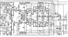
You are correct. The manual text does say "Class-B".
This is a significant over-simplification.
For more confusion, the circuit shows the output emitter voltages as "0V", which implies zero voltage across the emitter resistors, and zero current in the output devices (at idle in test).
But see the arrow at Q33. There is 60mA flowing. Not zero.
From no-signal to full signal, Class A is biased hotter than signal current. The device is never cut-off. Ideal Class B (never happens) is biased AT cut-off at idle, idle current is *zero*. Class C is biased past cut-off and is not common in audio because it can not reproduce a full waveform.
Ideally a class B stage fed small signal will smoothly rise from zero current to the current needed in the load.
But all our real devices have ZERO gain at zero current. We can not get a smooth rise from zero to small signal.
This is not a problem in tubes because they are very hard to cut-off. We would need huge drive signal to bring them all the way from near cut-off to normal working currents. "Class B" is usually a condition where idle current is very small, say 10% of full load current. In speech/music use this gives much better battery life, or lower electric bills in large transmitters. As even this is brutal to small sounds, non-battery tube amps tend to run richer, 20%-30% of maximum current at idle. This is often termed "class AB", indicating it is neither one nor the other. The tubes can approach cut-off, but only when the other tube is dominating the output. (If we get to 50%, it is class A.)
Transistors get down to very tiny current real easy. There are some bad examples of near-zero bias in some of the older cheaper transistor amps.
For any amplifier with some pretense of "quality" we apply some bias. For the usual emitter-follower design, we want the internal emitter impedance to be "small" compared to the load impedance.
Take just the Q33 Q34 pair and omit resistors. The transistors flow 60mA. Focus first on Q33. By Shockley's Law the emitter impedance is near 26r/60 or half an Ohm. The load is 4 Ohms or higher. 0.5 ohms is "small" compared to 4 Ohms. Even near idle, the stage has gain of 0.88, rising to no-more-than 0.9999 at high current. Gain changes 12%, which is greatly reduced by overall NFB.
But we really have six transistors acting like half-Ohm sources. But they have half-Ohm (0.47r) series resistors. So something like 0.17 Ohms driving 4 Ohms. And at high current (low emitter impedance one side, high on the other) it is still near 0.17 Ohms. Gain hardly changes at all. (This just touches the surface. R76 is there for a reason I do not care to puzzle out today. R72 and friends, Q31 Q29 and kin, reflect through the output devices as additional impedance. Not a trivial design.)
Note also that the total idle current is 180mA (0.18A) and the peak output current is around 16 Amps (64V/4r). The idle is about 1% of the peak. Far away from class A. "Practically class B." But that small current is enough to stay plenty away from true cut-off. The amplifier gain through zero output hardly changes.
Maybe the Japanese engineers use their terms differently, and the translator was not familiar with western technical language customs. It is possible that inside the Japanese *audio* community, transistor "class B" is "understood" to include enough idle current to say out of strict class B.
> L-08m service manual have better circuit description
You are correct. The manual text does say "Class-B".
This is a significant over-simplification.
For more confusion, the circuit shows the output emitter voltages as "0V", which implies zero voltage across the emitter resistors, and zero current in the output devices (at idle in test).
But see the arrow at Q33. There is 60mA flowing. Not zero.
From no-signal to full signal, Class A is biased hotter than signal current. The device is never cut-off. Ideal Class B (never happens) is biased AT cut-off at idle, idle current is *zero*. Class C is biased past cut-off and is not common in audio because it can not reproduce a full waveform.
Ideally a class B stage fed small signal will smoothly rise from zero current to the current needed in the load.
But all our real devices have ZERO gain at zero current. We can not get a smooth rise from zero to small signal.
This is not a problem in tubes because they are very hard to cut-off. We would need huge drive signal to bring them all the way from near cut-off to normal working currents. "Class B" is usually a condition where idle current is very small, say 10% of full load current. In speech/music use this gives much better battery life, or lower electric bills in large transmitters. As even this is brutal to small sounds, non-battery tube amps tend to run richer, 20%-30% of maximum current at idle. This is often termed "class AB", indicating it is neither one nor the other. The tubes can approach cut-off, but only when the other tube is dominating the output. (If we get to 50%, it is class A.)
Transistors get down to very tiny current real easy. There are some bad examples of near-zero bias in some of the older cheaper transistor amps.
For any amplifier with some pretense of "quality" we apply some bias. For the usual emitter-follower design, we want the internal emitter impedance to be "small" compared to the load impedance.
Take just the Q33 Q34 pair and omit resistors. The transistors flow 60mA. Focus first on Q33. By Shockley's Law the emitter impedance is near 26r/60 or half an Ohm. The load is 4 Ohms or higher. 0.5 ohms is "small" compared to 4 Ohms. Even near idle, the stage has gain of 0.88, rising to no-more-than 0.9999 at high current. Gain changes 12%, which is greatly reduced by overall NFB.
But we really have six transistors acting like half-Ohm sources. But they have half-Ohm (0.47r) series resistors. So something like 0.17 Ohms driving 4 Ohms. And at high current (low emitter impedance one side, high on the other) it is still near 0.17 Ohms. Gain hardly changes at all. (This just touches the surface. R76 is there for a reason I do not care to puzzle out today. R72 and friends, Q31 Q29 and kin, reflect through the output devices as additional impedance. Not a trivial design.)
Note also that the total idle current is 180mA (0.18A) and the peak output current is around 16 Amps (64V/4r). The idle is about 1% of the peak. Far away from class A. "Practically class B." But that small current is enough to stay plenty away from true cut-off. The amplifier gain through zero output hardly changes.
Maybe the Japanese engineers use their terms differently, and the translator was not familiar with western technical language customs. It is possible that inside the Japanese *audio* community, transistor "class B" is "understood" to include enough idle current to say out of strict class B.
> circuit of a Class A amp and a Class B amp may look very similar. ... little more than different resistor values.
Follow-on to that thought: see the string of 6 diodes at D8 D9, also VR2? If you put 2 more diodes in the string, or increased VR2 by about 100 Ohms, the "same plan" would run class A.
It would also run all-the-time about 4 times hotter than it ever gets in class B/AB, and burn its guts out. 'Same' schematic actually means very different physical build: heatsinks and transformer. (Which is why you never diddle a bias pot like VR2 carelessly.)
- Status
- Not open for further replies.
- Home
- Amplifiers
- Solid State
- appending class b amp after class A