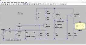
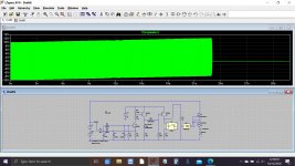
Is that low enough for dc protection?Trip occurs at around -/+2.5 volts DC.
This one does trip at +/-0.2V:
DC & Temp protection with limited resources
Last edited:
Its a pretty standard type of circuit so the amp designers must have thought it OK.
2.5v only gives 800mw dissipation in an 8 ohm load and so any speaker that such an amp would be used with should be safe.
2.5v only gives 800mw dissipation in an 8 ohm load and so any speaker that such an amp would be used with should be safe.

OK folks,
I've made the decision to accept a set of potential electronic and financial risks 😉 and do this:
For general retrofitting (e.g. my Trio Receiver, Vincent Monos, friends' applications) I am building a 15x22mm(32mm with 4xM3 mounting holes) DC detection & display board. This piggy backs on my 15x22mm(32mm with 4xM3 mounting holes) one-channel SSR board. The DC detector is based on the optocoupler SFH620A and does the SSR/V+ on/off switching, a green LED shows "SSR On" and a red LED signals "DC warning".
For my 4-way active DIY speakers, a 20x20mm board is designed to piggy back on the specialised SSR for this case which fits on the PwrAmp boards' Output Connectors and substitutes the "old" DC detector with electromechanical relay for the 4 Outputs (which avoids a bunch of cabling and connections).
Thanks for all the valuable input and work done! It will take a few weeks to build all that...
A happy, healthy Christmas Time to all!
Winfried
