Hi everyone!
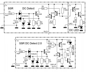
For my SSR project I have found a simple circuit to provide Amp Output DC indication (here in the forum).

Looking at this circuit I'm wondering if the follwong simplification would not have the exact same functionality while taking less space on a PCB (which is one of the reasons even thinking about simplification 🙄🙂 )
Thanks for educating me!
Regards,
Winfried
BTW: In my implementation the AC-off detection is done separately and therefore not of interest in this particular case.
For my SSR project I have found a simple circuit to provide Amp Output DC indication (here in the forum).
Looking at this circuit I'm wondering if the follwong simplification would not have the exact same functionality while taking less space on a PCB (which is one of the reasons even thinking about simplification 🙄🙂 )
Thanks for educating me!
Regards,
Winfried
BTW: In my implementation the AC-off detection is done separately and therefore not of interest in this particular case.
Attachments
Last edited:
If you only want DC fault indication then just place the LED in the collector load of T4 and omit everything else... or am I missing what you are trying to do?
You could use a high gain or Darlington (or FET) for T4 in that case.
You could use a high gain or Darlington (or FET) for T4 in that case.
Hi Mooly,
thanks for coming back so quickly!
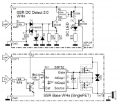
OK, let me clarify further what I want to do. A Schematic tells a thousand words:

I am "updating" my old active speakers which have a relay based output control. This uses a lot of wiring from the power amps to the relay circuit and then onwards to the drivers. I substitute the electromechanical relay by SSRs, the individual DC detection and muting control (which includes remote on/off, pwr on muting and AC loss detection in the "Fs" signal you see) to each power amp board (as "piggy back" PCBs).
Thanks and regards,
Winfried
thanks for coming back so quickly!
OK, let me clarify further what I want to do. A Schematic tells a thousand words:
I am "updating" my old active speakers which have a relay based output control. This uses a lot of wiring from the power amps to the relay circuit and then onwards to the drivers. I substitute the electromechanical relay by SSRs, the individual DC detection and muting control (which includes remote on/off, pwr on muting and AC loss detection in the "Fs" signal you see) to each power amp board (as "piggy back" PCBs).
Thanks and regards,
Winfried
Attachments
I don't think that will work as drawn. T5 will illuminate the LED all the time via conduction through its B-E junction.
When T4 turns on that will turn off T5 but the LED will remain lit as it is now supplied via T4.
You don't need T5. Just take the output from T4 collector and use a high gain or Darlington device here. It should be able to supply more than enough current.
When T4 turns on that will turn off T5 but the LED will remain lit as it is now supplied via T4.
You don't need T5. Just take the output from T4 collector and use a high gain or Darlington device here. It should be able to supply more than enough current.
Oooops! I'm so glad to have asked for advice!
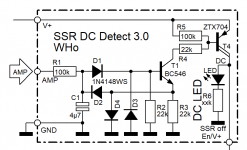
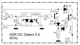
A quick search at Mouser yielded the ZTX704 PNP Darlington as suitable, because V+ can be up to +50V, although, the current draw is 20mA (max. probably 50mA) for LED and the SSR's Si8752 together. Here's the revised schematic:

It amazes me how simple the circuitry has become!
Cheers,
Winfried
A quick search at Mouser yielded the ZTX704 PNP Darlington as suitable, because V+ can be up to +50V, although, the current draw is 20mA (max. probably 50mA) for LED and the SSR's Si8752 together. Here's the revised schematic:
It amazes me how simple the circuitry has become!
Cheers,
Winfried
Attachments
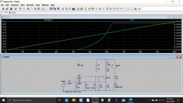
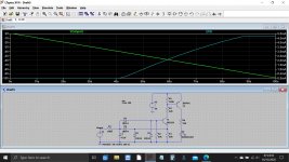
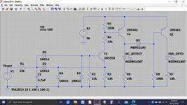
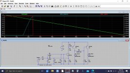
This is actually quite a good one to simulate 🙂
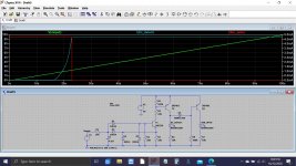
This shows the input voltage rising from 0 to +10 volts and also 0 to -10 volts. Supply is 50 volt.
You can see the LED current on the right hand scale and the voltages it trips at. Time is along the bottom.
This shows the input voltage rising from 0 to +10 volts and also 0 to -10 volts. Supply is 50 volt.
You can see the LED current on the right hand scale and the voltages it trips at. Time is along the bottom.
Attachments
Hello Mooly,
this is great! So, with this model it would be possible to optimise the circuit speed and e.g. the time it takes for the circuit to react to a failing Poweramp, right?
I do have an old version of LT Spice, but no experience with it, so could probably learn to use it by this simple circuit. Is it possible to share the model you have built so I could "play" with it? E.g. include the 5...10mA sink current the Si8752 builds, try different input time constants and so on.
Thanks and Regards,
Winfried
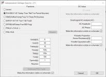
All things are possible with LT. Here is the .asc which will just click and run in either version of LT. You can add the Si8752 load either in series with the LED or as another parallel load. Series is more efficient but would be more difficult to alter the LED brightness to suit.
Attachments
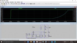
This shows a simulated output stage failure. The input voltage rises in 100uS to 50 volts DC. If you zoom in on the transition you can see how long the circuit takes to react (the C/R time constant)
You can also set the input up as a sine at full power and see how low a frequency you can get to before the circuit trips. That can be useful because you can gain 'trip' speed by sacrificing a little on max low frequency voltage allowable... and who listens to 100 watts rms at say 10 Hz.
So all easily tweakable.
Attachments
Hello to Skopje!
thanks for sharing your really simple approach! I'm a bit concerned about the threshold being in the >2V region, but I'll have a look into the SFH620A specs.
Mooly,
I've found a fatal mistake in the simplified Transistorcircuit (Einstein said: "Everything should be made as simple as possible, but not simpler!" 😀 ):
Switching the LED on upon DC detected is OK, but in that state the "SSR off" signal needs be off, not on! Conversely if the DC LED is on, the SSR current needs to be off! I'm currently modifying the circuitry to accommodate for that and will be back.
Regards,
Winfried
OK folks,
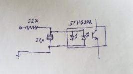
did some thinking (for what it's worth... 😉) about an implementation with the SFH620A-3, at the same time correcting my thinking mistake:

I hope this makes any sense... 😉 The idea is that D5 together with T5 Transistor and LED G switch off En/V+ current as soon as T4 turns on LED R (because Vce-T4 + Vf-LEDR < Vf-LEDG + Vbe-T5 + Vf-D5).
Chip, what's the actual Input DC trigger voltage threshold of the circuit you have implemented? To me it seems like >20V at the input are needed to open the OC Transistor because of the OC current transfer characteristics and the 20k resistor at the input (but I may be wrong).
Regards,
Winfried
did some thinking (for what it's worth... 😉) about an implementation with the SFH620A-3, at the same time correcting my thinking mistake:
I hope this makes any sense... 😉 The idea is that D5 together with T5 Transistor and LED G switch off En/V+ current as soon as T4 turns on LED R (because Vce-T4 + Vf-LEDR < Vf-LEDG + Vbe-T5 + Vf-D5).
Chip, what's the actual Input DC trigger voltage threshold of the circuit you have implemented? To me it seems like >20V at the input are needed to open the OC Transistor because of the OC current transfer characteristics and the 20k resistor at the input (but I may be wrong).
Regards,
Winfried
Attachments
Hello to Skopje!
Tschüss Bayern!
Switching the LED on upon DC detected is OK, but in that state the "SSR off" signal needs be off, not on!
Just put the phototransistor instead of T4 in post #3. Collector to V+, emitter to LED indicator.
Threshold voltage of LED inside optocouplers is usually about 1.1V. Actual threshold voltage will be higher than that depending on the used R. Some experimenting on the bench could be very useful.
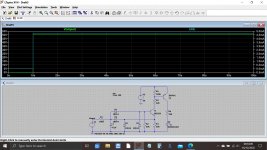
Have a play with this. R1 is altered to change the thresholds.
Trip occurs at around -/+2.5 volts DC. The two diagrams show the pos and neg trip operation and plot the two LED currents.
D5 is a Schottky for low forward voltage although a 1N4148 seems to work OK but gives less clean switching. Try it 🙂
Trip occurs at around -/+2.5 volts DC. The two diagrams show the pos and neg trip operation and plot the two LED currents.
D5 is a Schottky for low forward voltage although a 1N4148 seems to work OK but gives less clean switching. Try it 🙂
Attachments
Chip, what's the actual Input DC trigger voltage threshold of the circuit you have implemented? To me it seems like >20V at the input are needed to open the OC Transistor because of the OC current transfer characteristics and the 20k resistor at the input (but I may be wrong).
Regards,
Winfried
I use the phototransistor to trigger a small thyristor which shuts bias current and effectively disables the output stage. Since the thyristor needs very small current, only perhaps 200uA through LED input is sufficient to trigger. I think actual threshold is 6-7V. Initially I used 12k resistor but it appeared too sensitive.
So it depends how much current is required through phototransistor. For higher current reduce the resistor value and increase the capacitor to remain the time constant.
Bidirectional optocoupler is compact way, but two anti-parallel simple optocouplers can do the same function. Another advantage of optic solution is galvanic isolation of the sensing circuit and acting circuit (very useful in my case).
I'm a bit busy otherwise at the moment, but two observations anyway:
- the optocoupler approach is also taken in the "Ready-to-Run (RTR) SSR DC Speaker Protection and Delay" circuit.
- what about using Schottky Diodes as rectifier diodes instead of 1N914?
I'm a bit undecided at the moment which route to go. The OC thing is great for compactness. I've not yet tried LT Spice on either one myself...
Greetings,
Winfried
- Home
- Amplifiers
- Solid State
- App Output-DC-Detection with LED Indicator