Hi
The big thread of "100W Ultimate Fidelity Amplifier" is a chaos.
i need time to search through all the page and mark all i can find.
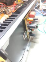
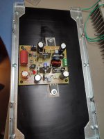
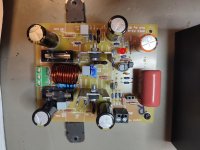
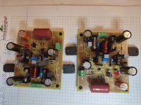
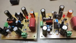
pcb is done in yellow by jlcpcb.
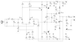
Gerber and all other documents are in post 13908: here
input BJT i use the recommended KSC1845, driver are 1381 and 3503, power mosfets are the renesas 1058/J162
as C4 it is written 220µF, and XRK use a polymer elco with 330µF. I use a orange 1000/16VµF by epcos
for C9,C16, C12, C15 i use Panasonic 680µF/50V
input cap is a red
 polymer panasonic 2,2µF/400V instead of 10µF
i use the lower gain setting R11, R12--> 550R and 20k
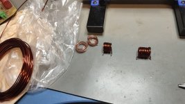
i did my first output coil...its not nice done but it has about 0,9µH the resistor is under the pcb
bias setting:
post 6686 bias at 100ma-170mA, wrote about goldmund amps--> bias 200-300mA
my bias is set according to the hint of post 7753 by bimo to 400mA. the amp is working fine.
post 6971 test by XRK as an Class A amp with 1,3A works fine...big heat sink is needed!
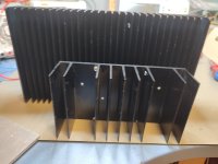
i used for the first test a 0,65K heat sink.
i plan to use a 4U/300 case by modushop with a 300VA 2x24V sec. transformer
i will just check the other channel.
psu voltage is 31 per rail and bias is after 2 hours 420mA stable. no heat problems, no smoke..
Gain is about 31dB, at 8ohm load about 29WATT.
if you have any hints , let me know.
edit:
Apex directory - done by XRK ..thx:
here:
edit: 26.8.2024: set bias current back to 400mA #post 104
edit: 25.03.2025: post 123 latest PCB Gerber by Peter(Kleinhorn) - thank you!
post 123
kr
chris
The big thread of "100W Ultimate Fidelity Amplifier" is a chaos.
i need time to search through all the page and mark all i can find.
pcb is done in yellow by jlcpcb.
Gerber and all other documents are in post 13908: here
input BJT i use the recommended KSC1845, driver are 1381 and 3503, power mosfets are the renesas 1058/J162
as C4 it is written 220µF, and XRK use a polymer elco with 330µF. I use a orange 1000/16VµF by epcos
for C9,C16, C12, C15 i use Panasonic 680µF/50V
input cap is a red
i use the lower gain setting R11, R12--> 550R and 20k
i did my first output coil...its not nice done but it has about 0,9µH the resistor is under the pcb
bias setting:
post 6686 bias at 100ma-170mA, wrote about goldmund amps--> bias 200-300mA
my bias is set according to the hint of post 7753 by bimo to 400mA. the amp is working fine.
post 6971 test by XRK as an Class A amp with 1,3A works fine...big heat sink is needed!
i used for the first test a 0,65K heat sink.
i plan to use a 4U/300 case by modushop with a 300VA 2x24V sec. transformer
i will just check the other channel.
psu voltage is 31 per rail and bias is after 2 hours 420mA stable. no heat problems, no smoke..
Gain is about 31dB, at 8ohm load about 29WATT.
if you have any hints , let me know.
edit:
Apex directory - done by XRK ..thx:
here:
edit: 26.8.2024: set bias current back to 400mA #post 104
edit: 25.03.2025: post 123 latest PCB Gerber by Peter(Kleinhorn) - thank you!
post 123
kr
chris
Attachments
-
 IMG_20231017_202306.jpg276.5 KB · Views: 382
 -
 IMG_20231017_202250.jpg358.9 KB · Views: 389
 -
 IMG_20231017_202834.jpg293.9 KB · Views: 370
 -
 IMG_20231017_185808.jpg339.6 KB · Views: 377
 -
 FX8_Bimo mod_2.jpeg187 KB · Views: 368
 -
 WhatsApp Image 2023-10-09 at 19.49.00.jpeg199.1 KB · Views: 327
 -
 IMG_20231016_203755.jpg390.3 KB · Views: 323
 -
 FX8_Bimo mod_4.jpeg224 KB · Views: 337
Last edited:

oh ....i forgot....C5 FB cap is 5pF mica...not 4,7µF
Voltages @31V supply rail and 420mA bias: both channels a very closed together so i write one channel :
input stage:
R5: 1,275V
R8: 1,412V
R6: 78,5mV
R9: 81,9mV
CCS:
R7: 1,294V
Driver:
R13: 1,468V
R14: 1,285V
R15: 0,61V
R17: 0,625V
Gate to Gate Voltage directly on the MOSFETS.....to have an idea .... is 2,74V
kr
Chris
Bias setup
done by prasi: post 9995
done by prasi: post 9995
| bias procedure |
| Procedure for bias. |
| 1. you will need 2 nos. of 10ohm 1W/2W resistors. |
| 1a. turn the trim pot so that resistance between first and third leg of trimmer is approx 250 ohm. |
| 2. Connect one lead these 10ohm resistors in series with your + and - rail wires of psu. |
| 3. connect the other lead of resistors to amplifier +/- supply connector on amp pcb. |
| 4. switch on supply and measure the voltage drop across these rail resistors. |
| 4a. measure the voltage between spk out and ground. this is offset. it should be less than +/-30mV. Good matching of Hfe of i/p transistor pair (Q1/Q3) will ensure that offset is close to zero. |
| 5. total quiescient current is given by I= V/10ohm |
| 6. set the pot so that voltage drop across 10 ohm rail resistors is about 1V to 1.1 V. |
| 7. Let the amp warm up for 1/2 an hour recheck the bias |
| 8. Adjust pot if required to have voltage drop of 1 to 1.1 V. |
| 9. This will ensure that you get a bias through o/p stage of approx. 100mA. |
Gain:
i matched the input BJT KSC1845 as high hfe as i can get from my batch. but 31dB is 4dB more then XRK wrote in post 7395:
Gain setting ...27dB
as i wrote i set the gain down with R11 and R12 550R and 20k.
could that be that the huge hfe at the input bjt transistors?
no sound check up to now.
i matched the input BJT KSC1845 as high hfe as i can get from my batch. but 31dB is 4dB more then XRK wrote in post 7395:
Gain setting ...27dB
as i wrote i set the gain down with R11 and R12 550R and 20k.
could that be that the huge hfe at the input bjt transistors?
no sound check up to now.
Last edited:
Gain:
i matched the input BJT KSC1845 as high hfe as i can get from my batch. but 31dB is 4dB more then XRK wrote in post 7395:
Gain setting ...27dB
as i wrote i set the gain down with R11 and R12 550R and 20k.
could that be that the huge hfe at the input bjt transistors?
no sound check up to now.
partly i answer myself about the gain 😉
post 7393
Thanks for the tips guys - before I saw Still4given's recommendation for BC550's I decided to test the amp out with BC546's with twisted legs. No matching or anything like that just stuck it in and set bias current to 175mA using external 10ohm safety resistors on the power supply leads. It plays music and sounds OK but the gain is very low compared to my other FX8 or FH9. I think at least it confirms that the PCB is good and no errors as it plays music. The VAS transistors get hot so I did not want to play too long. I am still waiting for the heatsinks to get in. In meantime I will check out Mouser or Digikey for KSC1845.
Is the lower gain simply a function of the feedback resistors or is it the much lower Hfe of the BC546 vs the 600 Hfe of the 2SC1845's? It sounds like maybe 20dB vs 31 dB which is where my other FH9 is at.
Here it is playing music with a pair of BC546's.
post 7398 about hfe by bimo mod
I think 2SC1845 will make S/N ratio slightly better. But the noise is not the most important in the power amplifier. I suggest you to choose highest hFE and matching them. It will make the distortion and DC Offset lower.
Good morning
short measurements with the Rchannel yesterday night evening.
8R is so far no problem
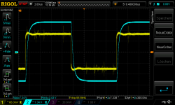
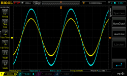
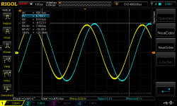
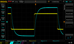
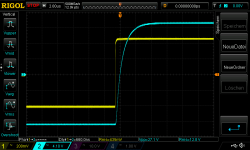
yellow ch1 on oscope is input
blue is ch2 the output
pic1 8R 31Vrail_420mVrms 1kHz input we get about 27 WATT...looks okay
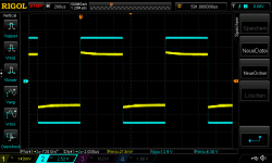
pic2 8R square with 100mVrms 60kHz input
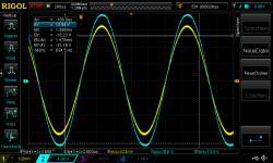
430m-440 Vrms input is about the max power without clipping--> 28WATT
short measurements with the Rchannel yesterday night evening.
8R is so far no problem
yellow ch1 on oscope is input
blue is ch2 the output
pic1 8R 31Vrail_420mVrms 1kHz input we get about 27 WATT...looks okay
pic2 8R square with 100mVrms 60kHz input
430m-440 Vrms input is about the max power without clipping--> 28WATT
Attachments
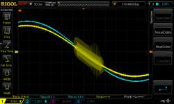
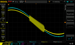
R channel with 4R i got oscillation problems on the input = yellow channel 1 scope ????!!!!!
at 4R load it start at 290mVrms input and gets bigger nearly at the max. (350mVrms input) of input and then it dissapears!
370mVrms is the max input and we get about 40Watt at 4R.
is that because the C5 with 5p is not correct. or is the gain in my amp too high.
as i remember my input Transistors ksc1845 had 470hfe and my driver trans about 137hfe.
any comment and help is very welcome because i use 4R loudspeaker
Attachments
good morning.
i changed the Rchannel pcb to the Lch pcb and i have the same issue.
so 2 options could be:
1. it is a measurement (scope probe without shield at th input terminal of the amp) behavior and i have no problems in "real life"
2. i have an oscillation problem on both channels
any ideas?
i appreciate your help
thx
chris
i did another test. with an extra probe.
i found that the oscillation is not before C5 and before R12 so at the "power side" of the amp is clean!
so the oscillation is at input stage what I probe around.
both channels
ideas?
i found that the oscillation is not before C5 and before R12 so at the "power side" of the amp is clean!
so the oscillation is at input stage what I probe around.
both channels
ideas?
no...why you ask?
IRF640 is a TO 200 housing and the datasheet says that you can have 125W.
i have no experience at TO 200 power mosfets....just keep Voltage and bias current
FX8 is without Rs ! with using of a Lateral MOSFET. these are very temp stable, therefore you are "safe" about temperature and possible overheating destroying the output MOSFET!
if you want to use them...look at XRK FH9- it is with vertical mosfets.
Success ! FX 8 is working oscillation free!!
why? i found a bad connection at GND on the fg!...🙄
why? i found a bad connection at GND on the fg!...🙄
here are some measurement with.
setup:
31Vrail power supply 4,45R 40WATT resistor load. amp mounted on a 4U/300mm heat sink (modushop)
bias 420mA.
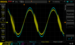
pic1 210Vrms input sinus is 10Watt on 4,45R at 200khz is fg..about 70,7% of 1khz signal
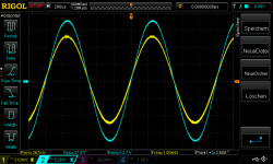
pic2 420mVrms input sine max power at 4,45R load about 39WAtt
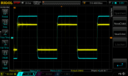
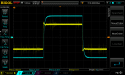
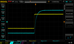
pic 3,4 210Vrms square to check ringing or slew rate
setup:
31Vrail power supply 4,45R 40WATT resistor load. amp mounted on a 4U/300mm heat sink (modushop)
bias 420mA.
pic1 210Vrms input sinus is 10Watt on 4,45R at 200khz is fg..about 70,7% of 1khz signal
pic2 420mVrms input sine max power at 4,45R load about 39WAtt
pic 3,4 210Vrms square to check ringing or slew rate
Attachments
-
 31Vrail_L_Ch_210Vrms in_4_45Rload_fg_200kHz 10Watt.png21.2 KB · Views: 89
 -
 31Vrail_L_Ch_420Vrms in_4_45Rload_1khz 39Watt.png23 KB · Views: 89
 -
 31Vrail_L_Ch_210Vrms 1kHz in_4_45Rload_square_slewrate_10Watt.png15.7 KB · Views: 87
 -
 31Vrail_L_Ch_210Vrms 1khz_in_4_45Rload_square_slewrate_10Watt_2.png13.6 KB · Views: 73
GAIN
any ideas why i have still 31db with the low gain setting R11 R12 (24db should be)
i check some BC550 or BC557 low noise but they have the some hfe range
ideas?
any ideas why i have still 31db with the low gain setting R11 R12 (24db should be)
i check some BC550 or BC557 low noise but they have the some hfe range
ideas?
What are your impressions now that it's working perfectly, do you recommend building this amp?Success ! FX 8 is working oscillation free!!
why? i found a bad connection at GND on the fg!...🙄
- Home
- Amplifiers
- Solid State
- APEX FX8 bimo mod