Replacing MN1526 & MP1526 for 2SC5200 and 2SA1943
I am building Apex A40 amplifier. Can someone suggest me if I can I replace MN1526 & MP1526 for 2SC5200 and 2SA1943? It would be very helpful.
The reason is that it is very difficult to find original 2SC5200 and 2SA1943 here in India. Most of them are selling fake transistors without themselves knowing that the items are fake.
I have some original MN1526 & MP1526s from Sanken. (I guess so).
I know that 1943s are 30Mhz and Sankens are 60Mhz.
For this reason I feel that amp with Sankens might oscillate.
The other option is MJL1302 & MJL3281. (Even these I have originals)
Kindly suggest. It would be helpful.
Ganesh
Hi,
I have built a P40 with 2SC5200 and 2SA1943. I am running it on +/-55V.
When 1 power it up for the 1st time both the fuses were blown. I replaced the fuses, remove the heatsink and power it up again and fuses are ok. When I measure the voltage for bias it was around 295mV. Offset was around 7V. Non of the trimmers have any effect on the readings. What could be the problem here? How can I find and fix the problem? I would appreciate any help/advise. Thanks.
Hi,
hard to say, try to measure semiconductors with diode tester,
I attach working simulation file to play,
BTW zero setting is exremely hard unless someone will do swap parameter of a position of potentiometer's slider,
regards
hard to say, try to measure semiconductors with diode tester,
I attach working simulation file to play,
BTW zero setting is exremely hard unless someone will do swap parameter of a position of potentiometer's slider,
regards
Attachments
Hi,
I have checked the 2SC5200/2SA1943 transistor with the diode setting on the multi meter and all looks ok.
I have hooked up a speaker and run a sine wave to see if I can get some sound. I could hear it, kind of distorted. the problem is all the 2SC5200, 2SC4793 and 1 BD139 get hot. R46, R47 and R48 were also quite hot. It looks like the problem is on the left side of the PCB. any suggestions what could be the problem? thanks.
Hi y'all,
Which PCB layout would be the latest for A40 Alex's rev 1.4?
I'm intending to build this soon
Which PCB layout would be the latest for A40 Alex's rev 1.4?
I'm intending to build this soon
Hi all, IAM having difficulty in finding bc550 and 560 in local market. What if I can use a1015 and c1815 in replacement or any other good replacement?
Make sure all transistors should be isolated from heatsink by using thermal tape or isolator use thermal paste for better heat transfer. Make sure there is no DC at outputHi,
I have checked the 2SC5200/2SA1943 transistor with the diode setting on the multi meter and all looks ok.
I have hooked up a speaker and run a sine wave to see if I can get some sound. I could hear it, kind of distorted. the problem is all the 2SC5200, 2SC4793 and 1 BD139 get hot. R46, R47 and R48 were also quite hot. It looks like the problem is on the left side of the PCB. any suggestions what could be the problem? thanks.
1015/1815 have different pinout, maybe see about BC546/556 (lower Hfe) or BC547/557 (possibly higher Hfe), but they are same pinout (CBE), but with slightly higher noise. Possibly look at ZTX450/550, same pinout (when looking at faceted face) with similar Hfe.Hi all, IAM having difficulty in finding bc550 and 560 in local market. What if I can use a1015 and c1815 in replacement or any other good replacement?
@apexaudio sorry for the tag,
Do A40 needs any big modifications to run on ±70VDC with 4 pairs of output transistors,
I want to increase it's output to 250/300W @ 8 ohms
Do A40 needs any big modifications to run on ±70VDC with 4 pairs of output transistors,
I want to increase it's output to 250/300W @ 8 ohms
hi did any one build this p30 pcb? i just finished this pcb. when i powered it up two 220 ohm resistors and bc 550 and 560 connected to these resistors are getting extremely hot and two 22ohm series resistors are also get hot. there is some voltage about 4.5v at the output too. still trying to troubleshoot 
Attachments
Hello All,
You guys are doing great work at diy community. Thanks to all… and special thanks to Mr. Mile and Mr. Alex


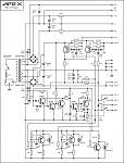
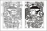
I recently tried to assemble Apex A40 using Alex`s PCB V1.5 but there is dc at the output.
I am testing it with +-29vdc, at the firs start both the trimmers were at the centre (half resistance) there was 11.4v DC at the output and supply voltage was decreasing (amp was consuming more current) and output transistors was overheating. Then I adjusted the bias trim pot to its max which is 114 Ohm (in my case, as I am using 500Ohm Trimmer with 150Ohm resistor connected in parallel under the board) Overheating of output transistors stopped but still there was 11.4vdc at the output.
I tried to study the schematics and PCB layout thoroughly suspecting that orientation of some transistor might be wrong, but found no errors. Checked the board very closely for shorting but none found. Checked each and every transistor again (I have tested it with Mtester before installing also) found no error. While studying schematics from A40 Long Technical I found R4 is 100 Ohm instead of 47 Ohm at the layout. Hence Installed 100 Ohms and now the voltage at output is 4.3v.
Where should I dig?
What might be the issue?
Is it because of BC550 and BC560 HFE difference. My BC550 have around 500 HFE and BC560 have around 200 HFE. But to be honest I have around 300 pieces of both in stock (bought it because I found it Original and at Cheap price). I have successfully assembled Apex P20, Apex P30 and Apex P30ZF using Alex`s PCB with the same BC550 and CC560. So I can say that those transistors are good.
The voltage at the emitters of T1 and T2 is +0.8 and -0.4Vdc does it means that there is imbalance somewhere?
Next 5551 and 5401 both are KEC make and have HFE of around 190 for 5551 and 170 for 5401.
My KSE340 and 350s are also original from trusted supplier.
Only BD139 is suspicious. thinking of It, can I use 2SD669AL instead of BD139? I have UTC make 669s in good quality.
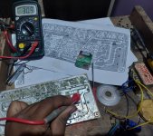
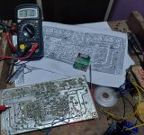
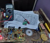
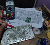
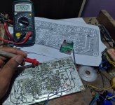
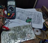
Request all of you to Please look the images and help me identify the issue.
Please note that the emitter resistor is .22 1W for testing purpose only and some components from zoble network is not installed. will purchase new one once dc at output gets below 10mv.
Thanks,
Neeraj
You guys are doing great work at diy community. Thanks to all… and special thanks to Mr. Mile and Mr. Alex
I recently tried to assemble Apex A40 using Alex`s PCB V1.5 but there is dc at the output.
I am testing it with +-29vdc, at the firs start both the trimmers were at the centre (half resistance) there was 11.4v DC at the output and supply voltage was decreasing (amp was consuming more current) and output transistors was overheating. Then I adjusted the bias trim pot to its max which is 114 Ohm (in my case, as I am using 500Ohm Trimmer with 150Ohm resistor connected in parallel under the board) Overheating of output transistors stopped but still there was 11.4vdc at the output.
I tried to study the schematics and PCB layout thoroughly suspecting that orientation of some transistor might be wrong, but found no errors. Checked the board very closely for shorting but none found. Checked each and every transistor again (I have tested it with Mtester before installing also) found no error. While studying schematics from A40 Long Technical I found R4 is 100 Ohm instead of 47 Ohm at the layout. Hence Installed 100 Ohms and now the voltage at output is 4.3v.
Where should I dig?
What might be the issue?
Is it because of BC550 and BC560 HFE difference. My BC550 have around 500 HFE and BC560 have around 200 HFE. But to be honest I have around 300 pieces of both in stock (bought it because I found it Original and at Cheap price). I have successfully assembled Apex P20, Apex P30 and Apex P30ZF using Alex`s PCB with the same BC550 and CC560. So I can say that those transistors are good.
The voltage at the emitters of T1 and T2 is +0.8 and -0.4Vdc does it means that there is imbalance somewhere?
Next 5551 and 5401 both are KEC make and have HFE of around 190 for 5551 and 170 for 5401.
My KSE340 and 350s are also original from trusted supplier.
Only BD139 is suspicious. thinking of It, can I use 2SD669AL instead of BD139? I have UTC make 669s in good quality.
Request all of you to Please look the images and help me identify the issue.
Please note that the emitter resistor is .22 1W for testing purpose only and some components from zoble network is not installed. will purchase new one once dc at output gets below 10mv.
Thanks,
Neeraj
Hello,hi did any one build this p30 pcb? i just finished this pcb. when i powered it up two 220 ohm resistors and bc 550 and 560 connected to these resistors are getting extremely hot and two 22ohm series resistors are also get hot. there is some voltage about 4.5v at the output too. still trying to troubleshoot
I am new here, but assembled P30 PCB 6 months back working fine without issue.
Please check Orientation of 2n5551 transistor, Just reverse it. It shuld be C B E, marking is correct but Orientation is incorrect.
As I suspected the issue might be because of HFE difference of BC550 and BC560, I replaced all BC560s with BC556 having HFE of around 300 and now the DC OFFSET is at 0.56Vdc. Means it came down from 4.3v to 0.56v. But it is still not manageble by the trimmer, no matter where I turn the trimmer, voltage remains constant. And the voltage at the emitters of T1 and T2 is now +0.7 and -0.5 which I guess is also a good sign.Hello All,
You guys are doing great work at diy community. Thanks to all… and special thanks to Mr. Mile and Mr. AlexView attachment 1443198View attachment 1443199View attachment 1443201View attachment 1443202View attachment 1443203View attachment 1443200
I recently tried to assemble Apex A40 using Alex`s PCB V1.5 but there is dc at the output.
I am testing it with +-29vdc, at the firs start both the trimmers were at the centre (half resistance) there was 11.4v DC at the output and supply voltage was decreasing (amp was consuming more current) and output transistors was overheating. Then I adjusted the bias trim pot to its max which is 114 Ohm (in my case, as I am using 500Ohm Trimmer with 150Ohm resistor connected in parallel under the board) Overheating of output transistors stopped but still there was 11.4vdc at the output.
I tried to study the schematics and PCB layout thoroughly suspecting that orientation of some transistor might be wrong, but found no errors. Checked the board very closely for shorting but none found. Checked each and every transistor again (I have tested it with Mtester before installing also) found no error. While studying schematics from A40 Long Technical I found R4 is 100 Ohm instead of 47 Ohm at the layout. Hence Installed 100 Ohms and now the voltage at output is 4.3v.
Where should I dig?
What might be the issue?
Is it because of BC550 and BC560 HFE difference. My BC550 have around 500 HFE and BC560 have around 200 HFE. But to be honest I have around 300 pieces of both in stock (bought it because I found it Original and at Cheap price). I have successfully assembled Apex P20, Apex P30 and Apex P30ZF using Alex`s PCB with the same BC550 and CC560. So I can say that those transistors are good.
The voltage at the emitters of T1 and T2 is +0.8 and -0.4Vdc does it means that there is imbalance somewhere?
Next 5551 and 5401 both are KEC make and have HFE of around 190 for 5551 and 170 for 5401.
My KSE340 and 350s are also original from trusted supplier.
Only BD139 is suspicious. thinking of It, can I use 2SD669AL instead of BD139? I have UTC make 669s in good quality.
Request all of you to Please look the images and help me identify the issue.
Please note that the emitter resistor is .22 1W for testing purpose only and some components from zoble network is not installed. will purchase new one once dc at output gets below 10mv.
Thanks,
Neeraj
Hence, next I will replace all BC550s with BC546s having HFE of arund 300. In this way both the new BC556 and BC546 will have HFE of around 300.
I have also replaced BD139 with D669 but no change in voltages. Hope an experts can answer if D669 will work fine there.
I also need to ask if I can replace 220uf 25v polar capacitor with 470uf 16v non polar capacitor? asking this because I already have 4 pieces of the same available.
will update the results after making above changes.
Thanks,
Replaced All BC550s, now I am able to adjust DC Offset and adjusted it near 2 - 4mV. As no heatsink is attached till now, adjusted the bias slightly just to take some readings.Hence, next I will replace all BC550s with BC546s having HFE of arund 300. In this way both the new BC556 and BC546 will have HFE of around 300.
Initial testing was done at +-30Vdc supply
1) The voltage at the emitters of T1 and T2 is now +0.62V and -0.63V
2) Base voltage for output transistor is now +/- 0.54V
3) DC at the output is fluctuating between -5mV to +5mV. (accepteble but slightly fluctuating because of the quality of BC546 used)
4) Voltage at the emitter pin of first bias transistor BD139 (D669 in my case) is -0.99Vdc and the voltage at Base & Collector of second bias transistor BD139 (D669 in my case) is +.98Vdc.
5) Voltage Between the emitters of Output transistors is kept at 5mV for testing purpose only.
According to my limited knowledge, all necessory voltages are taken and found accepteble, cheked if audio is there for couple of seconds and it was there.
I am really happy that it worked, Again I would like to thank Mr. Mile and Mr. Alex for such a wonderfull Amp.
Next. I will install proper heatsink, install missing components, increase the input voltage to +/- 50Vdc, re do the zero setting and bias setting, do some listening tests and stress test to check stability of my installed transistors. And parallelly, I will assemble the second channel too.
Will stick with the BC556 and BC546 instead of BC550 and BC560 as I my ears are unable to here any difference in sound quality or noise.
Hope this will be helpfull for newbies like me.
As the circuit and layout is tried and tested by experts, will update only if I found any problems with my transistor selection.
Thanks,
Attachments

I read the first post of this thread, and found information there. So I guess the answer to your question is..yes
HI, can you provide me gerber files. i can pay for your work muneeburrehman13@gmail.comSorry, but I will not, provide, gerbers for A40, because others, make, money, sealing boards copying my work .😡
- Home
- Amplifiers
- Solid State
- Apex A40 Amplifier Build Thread