There is no µ on a typewriter. micro starts with an m.
Remember that pico was only adopted in 1960, in Europe. Capacitors had been bought and sold for over 30 years at that point, there was no problem which demanded instand adoption of a new unit.
You didn't even have to know your units to get the right parts. It's not as tricky as snobs like to suggest. My brother was a purchasing manager, ordering caps this way, even over the phone. Maybe the suppliers snickered at his "mmmpf" but they supplied the right parts.
Micro starts with an m but the right symbol is µ which resembles a u rather than an m....
The experience is that it gave errors certainly when reading from schematics as writing "mf' and "mmf" makes that things are more easily overseen certainly when the then analog copy was wearing out. It is also a long time ago and superseded by Si unit prefixes/names for decades now. History....
The experience is that it gave errors certainly when reading from schematics as writing "mf' and "mmf" makes that things are more easily overseen certainly when the then analog copy was wearing out. It is also a long time ago and superseded by Si unit prefixes/names for decades now. History....
Last edited:
It really Hertz that we gave up Cycles Per Second.
It caused Mega Hertz (Ouch!)
Metric System?
In 1960, the US Government declared that we (USA) were going to go Metric.
Do not hold your breath (my breath holding record is 2 minutes and 45 seconds).
It caused Mega Hertz (Ouch!)
Metric System?
In 1960, the US Government declared that we (USA) were going to go Metric.
Do not hold your breath (my breath holding record is 2 minutes and 45 seconds).
The USA is in good company of Liberia and Myanmar. All leading countries in standardization 🙂
It is 1 Hertz and 1 kilohertz, Megahertz etc....
Positive is the numbering system of electrical parts like relays with a special function where the rest uses a different symbol which can also be a cause of mistakes. I can not even give an example as I forgot.
It is 1 Hertz and 1 kilohertz, Megahertz etc....
Positive is the numbering system of electrical parts like relays with a special function where the rest uses a different symbol which can also be a cause of mistakes. I can not even give an example as I forgot.
Last edited:
jean-paul,
I agree, I should have used the correct typing and spelling.
But the Pun is Mega Hurts, or Mega Hertz (needed to make the Pun work).
It is only an audio thing, merely audible (sound, not spelling).
And as to units, I used an electrical spectrum analyzer that had a scale setting for attowatts.
The most crazy set of units is velocity, expressed in GigaFurlongs per FemptoFortnight.
Try out plumbing stuff in Europe.... or tyres... Diameter in inches, width in millimeter, height in % of the width...
Some years ago I was helping out by replacing a copper water pipe and a defective water valve in an old dutch house only to discover the house had 14 mm copper piping where 15 mm is standard. No coupler I had with me was usable, just like the new 15 mm copper pipe. The plumber I went to smiled and told me the house had to be built somewhere in the 1900's as it has french 14 mm piping....
A guy I know works in a few musea and recently he had to fix an "installation" by a famous American artist that became defective. He could fix it and asked for permission but the artist insisted on American parts just like the device had. American parts are nowhere to be found here...
If one fixes stuff in various countries on a regular basis standards and standardization are more easily accepted 🙂
Last edited:
The guy that recommended 12k OPTs was probably thinking that I'd be using high impedance headphones. Would it hurt to use the 32 ohm ones?
If you would use higher impedance headphones the mismatch gets bigger, not smaller. If for example you would use 600 Ohm headphones, the primary impedance of the OPT would be: (600/4) x 12 K = 1.8 M.
I am not sure about the precise effect of using 32 Ohm headphones (which means the primary impedance will be 96 K). It will give less power than with a more suitable primary impedance but if you have enough power left this would not be a problem. I am not sure what it does to distortion levels so I hope that other forum members can tell you more about that aspect.
The most crazy set of units is velocity, expressed in GigaFurlongs per FemptoFortnight.
Gigafurlong = screaming "giddy up" to the horse over the last furlong. I'm assuming it's still related to the horse racing furlong.
Femptofortnight = maximum craving time for the fortnight player after stopping in detox?
Do OPTs need a load over them when the headphone is disconnected? I assume the negative feedback look path and grounding is good enough to provide that load if it was needed?
What tubes (if any) would be better suited for a 12k primary then? I really only prototyped this with 6cg7s because I had a couple of them in my stash. I was planning on getting a matched pair for the final build anyway, so it isn't much of an issue if I need to go with a different output tube. New OPTs would be an 8-week wait, so I'd prefer to use what I have there if possible. They're brand new too.
Thought I'd also add that it has more than enough gain, even at the lower voltages and with the feedback. Literally to the point of pain. I wouldn't have thought that there was an impedance issue judging merely from how it sounded. Very rich and detailed. Solid, clean bass and sparkly highs without too much harshness. Then again, I'm no audiophile. I looked at the output on my scope, and there was some distortion before feedback though. I attributed that to the 12AT7. More even than odd harmonics. The feedback seemed to knock that back considerably, but I'll admit that I have trouble determining the actual THD level. Haven't figured out how exactly. Feedback also effectively flattened a 100hz square wave. Little to no overshoot. Not sure how much any of that actually matters, but there it is nonetheless.
I am asuming you own a pair of these with 4 Ohm as secondary: EDCOR - GXPP10-12K
You could use them with pairs of 6K6's: https://frank.pocnet.net/sheets/049/6/6K6GT.pdf
If you prefer to use your OPT's with triodes, I advise you to look for triodes with a plate resistance somewhere between 2000 and 3000 Ohm. Connecting two equal triodes parallel per side of the OPT gives half the plate resistance of only one triode.
All the above is only valid if your secondary load is around 4 Ohm.
I am asuming you own a pair of these with 4 Ohm as secondary: EDCOR - GXPP10-12K
It turns out that I made one of my world-famous stoopid mistakes... Yes, that is the model of OPTs that I have, but the secondaries are 16 Ohm; Not 4 Ohm. Sigh... Still not ideal, but much better than the 4 Ohm. Sorry about that.
Last edited:
A common dropper on just *TWO* stages is normally quite stable. Moreso when one of them is a cathodyne ("unity" gain).
This still puzzles me.
The non-decoupled dropper becomes a shared load of the two stages. I would also expect that the balance of the cathodyne will be less good because of it.
If the amplifier is stereo, than the non-decoupled dropper becomes a shared load of the two stages of both channels.
The value of the dropper is not high (500 Ohm) but stlll I find it hard to believe that this is normal/good practice. I never saw this being done in a professional amplifier.
Attachments
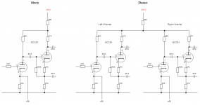
I think PRR meant a decoupled common dropper (as opposed to a decoupled dropper for the cathodyne followed by another decoupled dropper for the first stage). The schematic in the first post is missing the decoupling capacitors as you pointed out in post#2.
....stlll I find it hard to believe that this is normal/good practice.....
Then don't do it.
I was pointing out that it is not necessarily "fatal". But I agree it is suspicious. Particularly crosstalk.
I once built a single ended stereo amplifier using a pair of 45 output tubes.
Unfortunately, the single 6.3VAC filament secondary had to power a 6.3V dual triode driver filament; and the two type 45 tube filaments that were in parallel.
There were identical resistors in series with the 45 filament ends, the resistors dropped a total of 6.3V - 2.5V, at 3A filament current (1.9V per resistor).
Then, matched 25 Ohm resistors went from the 45 filament ends to the 820 Ohm common self bias resistor in parallel with a 1000uF bypass cap to ground.
The 25 Ohms, effectively in parallel to the two signal currents from the 45 tubes, was 12.5 Ohms.
That caused crosstalk of the signal of each channel into the other channel.
The channel separation was -40dB, across the frequency range of the amp.
The amp sounded very good.
After all, a very well adjusted cartridge and tone arm only have 30 or 35 dB channel separation, and that occurs only at mid range frequencies, and is less separation at low frequencies, and at high frequencies.
Now I have only one ear that nominally works. The other one only rings.
Not normal.
Analog, Digital. All One.
When I look at stereo recordings on a scope XY display, I often see a mostly thin line at 45 Degrees sloping up to the right (***).
What separation???
Only some stereo recordings have a more filled in and random pattern, often somewhat with approximately circular bounds, with the bounds according to the ppp to fff markings in the music, but with many lines and points everywhere within that particular size 'circle'. That seems like it just might have more separation than in (***)
Just my opinion.
Last edited:
- Home
- Amplifiers
- Tubes / Valves
- Anything overly bad here?