I read about this in an AudioXpress article (I think that's where I saw it) by Walt Jung about current sinks/sources. Mentioned LM317 as being pretty good, but limited by decreasing effectiveness with rising frequency. OK, so it's not the very best CCS, but it sure is easy to install.
My questions:
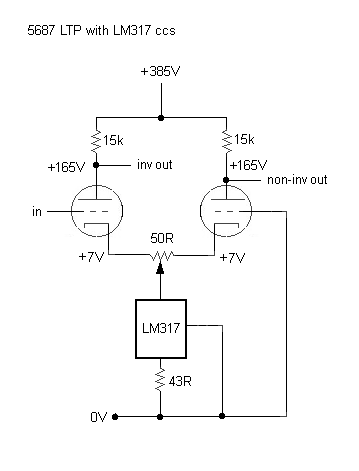
There is no negative supply, but there is 7V between the 5687 cathodes and ground. My understanding is that the LM317 needs at least 2.5 to 3 volts across it, which the above has. So it should work pretty well, right?
Would a negative supply of about -20V improve the performance of the LM317 in this case, or would it be about the same?
I know that there are discrete FET-based CCS circuits that will work better, but this was just soooo easy. Had to try it.
Thanks.
My questions:
There is no negative supply, but there is 7V between the 5687 cathodes and ground. My understanding is that the LM317 needs at least 2.5 to 3 volts across it, which the above has. So it should work pretty well, right?
Would a negative supply of about -20V improve the performance of the LM317 in this case, or would it be about the same?
I know that there are discrete FET-based CCS circuits that will work better, but this was just soooo easy. Had to try it.
Thanks.
But the discrete MOSFET CCS has only two transistors and three resistors, with performance many orders of magnitude better. The 317 is a very, very mediocre CCS, and at high frequencies, it's downright awful.
In any case, unless you have a need to keep the plates at the same DC voltage, you can lose the trimmer. At that value, it's not doing very much anyway.
In any case, unless you have a need to keep the plates at the same DC voltage, you can lose the trimmer. At that value, it's not doing very much anyway.
I tried this with a russian 6N6 with 22kOhm plate resistors and 75Ohm in the CCS. The output is within 1 dB up to 60kHz.
The right triode has a little bit more distortion but when you use it for example to drive a EL34 or a KT88 this distortion is lower than 0.1%
The right triode has a little bit more distortion but when you use it for example to drive a EL34 or a KT88 this distortion is lower than 0.1%
I was told that all 317 are not equals and some use different mask/design ! ?But the discrete MOSFET CCS has only two transistors and three resistors, with performance many orders of magnitude better. The 317 is a very, very mediocre CCS, and at high frequencies, it's downright awful.
Agreed 100%, don't care about static plate voltage, this does not affect the symmetry of the output signals, no more than tube mismatch.In any case, unless you have a need to keep the plates at the same DC voltage, you can lose the trimmer. At that value, it's not doing very much anyway.
The weakest tube just limits the output swing, the other follows !
The only important thing is to use equal plate load, don't forget to include the grid leak resistor of the next stage.
Yves.
Thanks for the replies.
I'm going to try the FET CCS soon. I did slap the 317 in there (it's actually in the tail of a 6N30P pair DC-coupled to a pair of 2A3's), and thought I noticed an improvement. I just wanted validation, I guess. Now the next thing to do is to improve it some more by using a *real* CCS down there.
I'd be glad to lose the pot if I don't need it. The DC voltages can vary a little without causing problems.
I haven't been able to find a 'cookbook' step-by-step for designing a proper FET CCS. I think I have a schematic saved, but the last time I looked at it, I got lost trying to find the correct value for the current-setting resistor. Is there a site that goes step by step how to find correct values?
It's easy. Do a MOSFET cascode like the one in my phono preamp article. Adjust the source resistor to get the correct current by driving a fixed resistor from the CCS and measuring the voltage across it.
Thanks SY. I'll have a look at your phono pre article...
Opinions on IXP10M45S? As in this?:
Current Source
Opinions on IXP10M45S? As in this?:
Current Source
Hi again...
On page 10, "Design Integration and Details", there's the schematic for the audio circuit. In the cathode follower (output buffer), there's a CCS of two DN2540 in the cathode circuit.
Is R18 the current set resistor (the one whose value would be changed to vary the current output)?
In the first (input) stage, there's a 1k ohm resistor (R3) placed below the CCS. (R5 would be the current set resistor, correct?) This is part of the load for the current source, correct?
If yes, then one could concoct a test circuit by using just that part of the circuit. Connect R3 to ground, and feed the "top" of the CCS with a smaller voltage, say +15V. Adjust the value of R5 for the desired current.
Correct?
Thanks again...
R18 is indeed the current-setting resistor. The other two are gate-stoppers. The nice thing about this sort of CCS (besides simplicity and high performance) is that it's a two terminal device so can be used as source or sink.
Yes, you can adjust it exactly that way- a 1k dummy load has the advantage of having 1v/mA of drop, so (for example) a 5 volt drop corresponds to 5 mA.
And the CCS will want at least 5-10 volts across it. That means you'll probably want to return it to a negative rail. Fortunately, because of the stunningly good power supply rejection that a high performance CCS brings to the table, the supply can be very simple and its exact voltage doesn't matter.
FYI, if you want a high compliance CCS with a low voltage budget (i.e., avoiding a negative supply), a bipolar current mirror will do well. Without emitter resistors, it is possible to have constant current down to 0.1V or so. However, the Early effect is exaggerated, so the current will be noticably higher at, say, 10V (it's not a very constant current). For any higher accuracy, you have to sacrifice more voltage drop, e.g. 0.7V for a Wilson mirror, or a "ring of two" source.
An op-amp servoed circuit like this
can work to arbitrarily low voltages, but requires an additional rail (maybe +10V for the op-amp, though it's low current), and the arbitrariness of the saturation voltage depends on the op-amp gain and offset. Bandwidth is limited by op-amp and Cgs, which can be fairly high; above that, the output appears largely capacitive due to miller effect.
FYI, LM317 input is an open collector, so it's not a terrible CCS. LDOs are much worse (emitter/source to Vin). What are the actual numbers on its input impedance at HF, does someone have a plot? I forget if the datasheet does, I know I've seen PSRR before but that's not the same as dynamic impedance.
Tim
An op-amp servoed circuit like this
An externally hosted image should be here but it was not working when we last tested it.
can work to arbitrarily low voltages, but requires an additional rail (maybe +10V for the op-amp, though it's low current), and the arbitrariness of the saturation voltage depends on the op-amp gain and offset. Bandwidth is limited by op-amp and Cgs, which can be fairly high; above that, the output appears largely capacitive due to miller effect.
FYI, LM317 input is an open collector, so it's not a terrible CCS. LDOs are much worse (emitter/source to Vin). What are the actual numbers on its input impedance at HF, does someone have a plot? I forget if the datasheet does, I know I've seen PSRR before but that's not the same as dynamic impedance.
Tim
FYI, LM317 input is an open collector, so it's not a terrible CCS. LDOs are much worse (emitter/source to Vin). What are the actual numbers on its input impedance at HF, does someone have a plot?
I think that's in Walt Jung's AudioXpress article "Sources 101: Audio Current Regulator Tests for High Performance, Part 2" on page 1, fig. 10B.
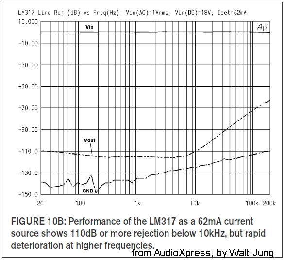
That's labeled "line rejection" so I suppose that means PSRR, not input impedance.
The graph is taken from copyrighted material written by Walt Jung as published in AudioXpress, so I'm hereby attributing it to its rightful source.
the CCS will want at least 5-10 volts across it. That means you'll probably want to return it to a negative rail.
Well, that's the problem in this particular amp -- I'd have to put in a negative supply. No bias taps or anything convenient like that in there now. But I have some wee little xfmrs I could use (they're 40VCT at something like 50mA). Yeah, I should do that... But the LM317's dropped right in, cathodes to ground. In this case, there's 9V across the LM317, which should be plenty. But it looks like that wouldn't be enough for the two-DN2540 ccs...
SY, thanks for bearing with me through all these questions. I think I finally have an adequate handle on that dual-DN2540 regulator, and I'll definitely be using it. I'm at a stage now where I'm tweaking a couple of amps I've had built for a long time. I think of them as prototypes. Even a simple common-cathode 5687 line stage holds many mysteries to unlock.
I bought a copy of "Valve Amplifiers" a few months ago, and reading it has really got the wheels spinning.
Hey, come to think of it, I have another line stage built that's a perfect candidate for a ccs plate load. The B+ is about +215V, IIRC...
You may also lift both grids few volts above the ground . . . not necessarly simpler . . .. . .
Well, that's the problem in this particular amp -- I'd have to put in a negative supply. No bias taps or anything convenient like that in there now. . .
Yves.
Well, do remember that the voltage across the CCS has to accommodate the AC voltage swing. So if the static cathode voltage is 7V and your input voltage is 6V peak-to-peak or 3V peak (about 2V RMS), you'll have that cathode voltage swing down to 7V - 1/2(3V) = 5.5V and likewise swing up to 8.5V. That's still probably enough for the CCS, but it's pushing things. A negative rail is pretty simple, or for the cost of two caps, you can follow Yves's suggestion and float the whole thing up several volts.
Yeah, Valve Amplifiers is a terrific book. I suspect that the FET cascode CCS will find its way into the 4th edition.
Yeah, Valve Amplifiers is a terrific book. I suspect that the FET cascode CCS will find its way into the 4th edition.
Well, do remember that the voltage across the CCS has to accommodate the AC voltage swing. So if the static cathode voltage is 7V and your input voltage is 6V peak-to-peak or 3V peak (about 2V RMS), you'll have that cathode voltage swing down to 7V - 1/2(3V) = 5.5V and likewise swing up to 8.5V. That's still probably enough for the CCS, but it's pushing things. A negative rail is pretty simple...
Looks like a 9V bias would be just barely enough to work with the CCS. Agreed that a negative rail is simple enough, though. I'll add one eventually, then try my hand at this cascode depletion mode MOSFET CCS.
So if the static cathode voltage is 7V and your input voltage is 6V peak-to-peak or 3V peak (about 2V RMS), you'll have that cathode voltage swing down to 7V - 1/2(3V) = 5.5V and likewise swing up to 8.5V.
I have general questions about how one goes about figuring this, for cascading stages without overload. Should I start a different thread, or ask in this one?
OK, first question... Inspired by "Building Valve Amplifiers" and its discussion of the CD-standard 2V rms level...
Say you wanted to have a single-ended common-cathode triode stage after your CD player, and the volume control would be at the output of that stage (not the usual location at the input, but just say we want to do it this way)...
2V rms = 2 * 1.414 = 2.83V peak
Peak to peak of 2V rms = 2 * the peak voltage (2 * 2.83Vpk) or 5.66V pk-pk
1) Is that correct? If yes, then I have another question...
2) If cathode biased, the voltage at the cathode has to be set high enough so that the signal from the CD player does not drive the triode into grid current. What voltage does that need to be (at minimum)?
- Does it need to be at least +3V, to comfortably accommodate the *peak* voltage?
- Or does it need to be at least +6V, to accommodate the *peak-to-peak* voltage?
3) Now for the most difficult question: In terms this dummy can understand... Why?
TIA.
--
2V rms = 2 * 1.414 = 2.83V peak
Peak to peak of 2V rms = 2 * the peak voltage (2 * 2.83Vpk) or 5.66V pk-pk
1) Is that correct? If yes, then I have another question...
2) If cathode biased, the voltage at the cathode has to be set high enough so that the signal from the CD player does not drive the triode into grid current. What voltage does that need to be (at minimum)?
- Does it need to be at least +3V, to comfortably accommodate the *peak* voltage?
- Or does it need to be at least +6V, to accommodate the *peak-to-peak* voltage?
1. Yes, it is. Now remember, as that signal swings negative, you're moving away from the grid current region, so the concern is the positive part of the swing.
2. Depends on the tube. Nominally, grid current starts at Vgk = 0, but lots of tubes will show grid current before that point and consequent distortion. If memory serves, Morgan showed some data about that. It's a good reason to design the stage so that you never go positive of (say) -1V and/or you keep the driving impedance low to minimize distortion from the effective variation in the load because of variable grid current.
Let's take an example. We have a 12AX7 with a red LED in the cathode providing 1.7V of cathode bias. Now this is a tube which has grid current issues well before the Vgk = 0 hard clip point, so we want to make sure that Vgk never goes positive of -1V. At idle, Vgk is -1.7V. So the positive-going side of the signal shouldn't exceed 0.7V peak, or (about) 0.5VRMS.
$. Remember the Fourth Son from the Passover ceremony (or google it). Here's the answer to the question you didn't ask. You also have to account for what the swing will do at the plate. If you lay out the load line, you may find that you have distortion and clipping in the negative direction because of running the tube toward cutoff. That provides an additional constraint for determining if a stage will overload with the expected input signal. As you can imagine, it's a problem which is especially acute for high mu tubes.
Thanks for that.
OK, in the case of the 12AX7, the limit is where the onset of grid current happens. So...
Now, if we know that we're going to have 2V rms coming in from the output of a CD player, then I have a particular real-world problem...
I have a 5687.
I have the output of the CD player feeding the 5687 grid. No coupling cap. 100k grid leak resistor for the 5687.
I remember Morgan's discussion culminating in a general rule of thumb that grid current can be expected at grid bias of -1V or lower. I think he used ECC88 as the example, but I don't remember.
So let's say -1V is the limit.
OK, with 2V rms out from the CD player, that's 2.83V pk.
If I use two red LEDs in series from cathode to ground, I get -3.4V grid bias on the 5687. That would seem to be OK at first glance. However, that +2.83V peak swings down to within about -0.6V grid bias. Is that going lower than our 1V limit, so we're likely to introduce a little grid current on peaks?
If so, then 4.1V (two LED's and a 1N4148 in a string) should be more than enough, with plenty of headroom.
Did I figure that right, or am I way off?
Or does the pk-pk voltage have something to do with it that I'm missing?
OK, in the case of the 12AX7, the limit is where the onset of grid current happens. So...
we want to make sure that Vgk never goes positive of -1V. At idle, Vgk is -1.7V. So the positive-going side of the signal shouldn't exceed 0.7V peak, or (about) 0.5VRMS.
Now, if we know that we're going to have 2V rms coming in from the output of a CD player, then I have a particular real-world problem...
I have a 5687.
I have the output of the CD player feeding the 5687 grid. No coupling cap. 100k grid leak resistor for the 5687.
I remember Morgan's discussion culminating in a general rule of thumb that grid current can be expected at grid bias of -1V or lower. I think he used ECC88 as the example, but I don't remember.
So let's say -1V is the limit.
OK, with 2V rms out from the CD player, that's 2.83V pk.
If I use two red LEDs in series from cathode to ground, I get -3.4V grid bias on the 5687. That would seem to be OK at first glance. However, that +2.83V peak swings down to within about -0.6V grid bias. Is that going lower than our 1V limit, so we're likely to introduce a little grid current on peaks?
If so, then 4.1V (two LED's and a 1N4148 in a string) should be more than enough, with plenty of headroom.
Did I figure that right, or am I way off?
Or does the pk-pk voltage have something to do with it that I'm missing?
The grid-current-onset voltage is different from tube to tube. In the case of a 5687, the mu is much lower so the chances are that you can swing the input closer to zero.
But let's return to that Fourth Son. The mu of the 5687 is about 18, so for any reasonable load, you'll have a gain of 14 or so. That means your 2V signal is now 28VRMS or nearly 80V peak to peak. Is that what you really want?
But let's return to that Fourth Son. The mu of the 5687 is about 18, so for any reasonable load, you'll have a gain of 14 or so. That means your 2V signal is now 28VRMS or nearly 80V peak to peak. Is that what you really want?
Hmmm... Now the can o' worms is wide open...
The reason I was asking is precisely that I don't think I understand the proper gain structure from stage to stage. So in the broadest sense I guess I'm asking for help designing my audio system(!).
In a 'normal' system, the CD puts out 2Vrms, then there's a volume control, where you throw away a lot of that voltage, and then make it back up with at least three stages of gain -- the control amp and a power amp of at least two stages. Or you can have a 'passive preamp' going to a power amp, which if it's a tube amp will usually have three stages.
I built a Mullard 5-20 style amp in a Dyna ST70 chassis. It had a 6DJ8 common-cathode stage DC-coupled to a 6SN7 Schmitt inverter, RC-coupled to triode-wired EL34s. It was OK, but had way too much gain to be used with any kind of preamp with gain. So I decided to split out that first stage and make it a 'control amp.' The lowest-gain triode I have around is 5687, so that's what I used for that first stage.
From there, I decided I'd put the volume control on the output of the control amp, for no better reason than that I followed someone's advice who thought it would sound better that way. (the low output Z of that tube'll drive the crap out of the pot, jacks and those cables...) And that's how I wound up with a 5687 line amp with a 50k pot on its output.
That feeds a push-pull power amp with a 6N30P LTP DC-coupled to a pair of 2A3's. (No global feedback.)
I wonder if the voltage gain of the stages works? Let's see...
If I start from the output of the system, the 2A3's are operating at Ep = 250V, Ek = -42V.
The 6N30P has Ep = 200V, Ek = -9V. 6N30P is loaded with a push-pull choke in the plates (actually the primary of a push-pull OPT designed for EL84s).
Looking at this with what I (think I) now know...
6N30P mu = 15. In circuit, let's say 14. In an LTP, is the mu halved? Or is that just if you use one output instead of two? Let's say it's all there because we're talking push-pull...
So mu = 14. You can probably swing up to 42Vpk (84Vpk-pk) to the 2A3's, so an input voltage of 42/3 = 14Vpk should do the trick. (Or is that 42Vpk-pk?)
14Vpk/1.414 should give us the rms voltage, so about 10Vrms is required to drive the 2A3's.
Since the mu of the 6N30P is about 14, only 0.7Vrms is required at the input to the power amp to drive it to full power... Really???
If that was all correct, then I'll be re-thinking this system from the output back to the input... A CD player can drive my power amp well into clipping??? Who knew?
I'm sure I goofed that all up somehow. Let me know...
Last edited:
- Status
- Not open for further replies.
- Home
- Amplifiers
- Tubes / Valves
- Anything horribly wrong with this (LTP w/ LM317 as CCS)