Going back a step, did you have specific problems or concerns as to why you wanted to include inrush control?
One practical hassle could be tripping a mains feed cb, which can happen as transformer VA gets larger and larger. The same may go for the mains inlet fuse in your equipment. Both of those issues go to detailed awareness of the inrush waveform, and the protective device trip conditions.
The system has a very primitive set of low pass filters - one at the reservoir (6mF giving 1Vp-p ripple), each output stage a 200uF and the input stages 150uF caps. In total about 7mF. The toroidal transformers (hammond) I'm considering have 1.1A 225VA or 1.3Arms 300VA which would be fine for normal operation but poses a challenge for capacitative inrush. I've managed to model this under 3A but the transformers probably would still not be happy on a daily basis.
I've been looking at this a little - if I went switched then a PFC-boost would give 390V but without isolation (which I'd be happier with for safety). At this point most of the flyback systems are targeted at digital <100V, and it seems 250-300W is the cusp of switching to a LLC resonant system (and still keep above 90% efficiency). A PFCboost isolated LLC resonant output 250-300W at 200-250V would be good.
So as a concept, PFC-boost to 390V then something like this https://www.ti.com/tool/PMP10949 to get to 200V output at 2.6A for 520W with high efficiency.
Although a half wave bridge output - it's possible to make a full wave ripple cancellation - have a look at fig 9: https://gansystems.com/wp-content/u...Designing-an-AC-DC-LLC-Converter-with-PFC.pdf
Could you elaborate on what the 'challenge' and 'would still not be happy' relate to? Is there some kind of damage or service life degradation of parts that is going to happen?The toroidal transformers (hammond) I'm considering have 1.1A 225VA or 1.3Arms 300VA which would be fine for normal operation but poses a challenge for capacitative inrush. I've managed to model this under 3A but the transformers probably would still not be happy on a daily basis.
Could you elaborate on what the 'challenge' and 'would still not be happy' relate to? Is there some kind of damage or service life degradation of parts that is going to happen?
Well given the LTSpice model shows a 50A inrush potential, I would expect following the chain:
* CB trigger
* fuses blown
* transformer winding damage
* rectifier diode damage
* capacitor's ripple current rating at 100Hz is ~17A at 450V. Add the others in parallel that's roughly 25A.
The challenge to me is to keep the current close to the operational draw on startup to not shorten the lifespan with maybe one or two power ons a day.
Ok I can see where your concern is coming from now.
Perhaps I can suggest that you most likely won't in practise experience any damage. Certainly there is some risk, as the actual current levels and durations aren't known, and it does depend on the mains feed impedance you have available, plus the impedances of your parts. Imho you would gain more from measuring and gaining a better understanding of the AC surge current aspect.
For example, you may have a digital scope and an isolated current transducer that together can measure actual inrush current waveforms and their levels. You can then start with measuring just the (or a) transformer inrush with no secondary loading. If you do that at least 10 times, then you should be able to confidently identify the worst-case inrush peak, and profile, when using just a simple mains switch. You can then assess that profile against CB and fuse characteristics. The link below indicates one way to do that for fusing.
You could then add an example load/filter, and do another 10 inrush measurements to see how additive the result is (it is unlikely to be additive due to the dynamic inductance characteristic of the primary). You could use all that data to update your LTSpice modelling.
https://www.dalmura.com.au/static/Valve%20amp%20fusing.pdf
With respect to diode surge current capability, there is some relevant discussion in the first section of this link:
https://www.dalmura.com.au/static/Power%20supply%20issues%20for%20tube%20amps.pdf
Capacitor ripple current relates to continuous operation - it is almost 'impossible' to damage a capacitor from a single surge/discharge - I am sure there would be a damage level, but given the capacitor is on the secondary side of a transformer, and past the diodes, I just can't see it happening. You could (and perhaps should) try to simulate the worst-case prospective charging current, and confirm that by measurement.
Last edited:
The capacitor inrush is about 350J (capacitive) if uniform over 1 second is 350W, but as this is AC, the inrush for a cycle is about 550W. I'm deliberately forcing the cathode bias up and pinning the grids to 0V to force a negative bias on startup.
Initial approach is an NTC+bypass on the transformer and a 500W 2.2K resistor, then 3x50W then a single 50W in a stepped bypass operation. However let me get the transformer, bridge, capacitor and resistor in and look to see what we're getting.
That 500W resistor.. is 330x80x10mm and would hit a temp of 200+degC if not bypassed. I need to find a heatsink. I suspect as this is only used for 15 seconds with the power dropping off from 500W, it will get hot. However this is the best option (rather than ten 50W inside the cover).
At a later date I'll look into PFC and a higher voltage SMPS, but the transformers/inductors to get that power are almost as expensive as a linear.
Last edited:
NickKUK, you indicate there is a regulator - does that power a valve amplifier?
Is the amplifier circuitry instantly requiring full load current at the start of energisation?
You identify 7mF of capacitance that needs to be charged up on initial energisation, and identify 350J to do that. Is all the capacitance getting charged to the same voltage, ie. 330V ? Is all of that capacitance the bulk filter capacitance after rectification, or is some of it buffered (eg. RC filtering) ?
NickKUK, you indicate there is a regulator - does that power a valve amplifier?
Is the amplifier circuitry instantly requiring full load current at the start of energisation?
You identify 7mF of capacitance that needs to be charged up on initial energisation, and identify 350J to do that. Is all the capacitance getting charged to the same voltage, ie. 330V ? Is all of that capacitance the bulk filter capacitance after rectification, or is some of it buffered (eg. RC filtering) ?
Yes - an OTL amp with solid state rectification and no active regulation. 7mF is obscene for a tube amp. 6mF provides a 1v p-p output ripple at normal operating current as a 1st order LPF. Separate 1st order LPF then sit on the output banks (200uF) and frontends (150uF).
I could go for regulation - although my modelling hasn't been able to deliver the low Vripple from 20Vpp for example that would allow a smaller reserve cap.
So as you can see this is brute force low tech approach.
Ta. So the amp loading won't start straight after turn-on due to valve heater warm-up time?
Is only 0.2 + 0.15 = 0.35mF of capacitance RC buffered, or are there many more RC buffered filters ? What is the time-constant of the RC filters?
How large (VA) is the power transformer and is there only 1 PT ?
Is only 0.2 + 0.15 = 0.35mF of capacitance RC buffered, or are there many more RC buffered filters ? What is the time-constant of the RC filters?
How large (VA) is the power transformer and is there only 1 PT ?
Ta. So the amp loading won't start straight after turn-on due to valve heater warm-up time?
Correct:
0. T+0 output muted (0V).
1. T+1s Heaters - start+11s B+ ready but I will simply leave it to start given the natural slow start. Heaters on a separate toroidal transformer
2. T+0s Neg Bias at 24V on cathode - this reduces the idle current but not eliminate completely. At start+15sec this should be switched off
3. T+0.5 max NTC on the primary side switched out
Inrush switching - steps:
4. T+0 - T+11 200R inrush limit (500W max)
5. T+11 - T+15 56R inrush limit (3x168R 50W in parallel)
6. T+15 - T+19 16R 50W.
7. T+15 - cathode bias and 0V grid clamp released.
8. T+19 - inrush bypass switched
9. T+20 mute released.
Just realised I have a minor boo-boo - currently have 10x2K 50W in the design to give 200R at 500W, but I'm looking at 2.2K 500W not a 200R 500W. Will recheck.
Is only 0.2 + 0.15 = 0.35mF of capacitance RC buffered, or are there many more RC buffered filters ? What is the time-constant of the RC filters?
Per channel - one 150uF+1K on each B+ input stage (2x12BH7A triodes), although I want reserve for adding a second tube here.
Per channel - one 1K+150uF and one 200uF+2K in the output stage (4xecc99 triodes) B+. Here I want reserve to switch to PP at some point.
How large (VA) is the power transformer and is there only 1 PT ?
This I'm flexible on as looking to see what I need. 225VA or 300VA common for both channels. That's 240V primary, secondary 220V at 1.03A (225VA) or 1.3A (300VA) hammond toroidal. Heaters on a separate 12V toroidal.
And I see your point about mF vs uF. 6000uF + 2x150uF + 2x(1x150uF+1x200uF) = 6000uF + 1000uF = 7000uF = 7mF.
Last edited:
Do you have ball-park primary and secondary winding resistances for such a PT? Perhaps ask Hammond?
Have you then checked what the maximum charging current can reach on the rectified secondary winding (eg. using PSUD2)?
Have you then checked what the maximum charging current can reach on the rectified secondary winding (eg. using PSUD2)?
Do you have ball-park primary and secondary winding resistances....
What, actual numbers? What are you, an objectivist?
(You don't even have to ask. Hammond publishes numbers on those things.)
Pulling a random 300VA 300V donut off Hammond I get well under 30 Amps. In my house in the woods, 44 Amp line surges cause no trauma and little lamp-flicker. I would not much worry about a <30A surge even on my poor little generator.
Attachments
Yeh I searched Hammond and located the 225VA and 300VA toroids but there was no on-line data that identified winding resistances - hence the suggestion to contact Hammond.
The peak charging current and profile will depend on the mains voltage configuration too a bit. Ballpark indication from PSUD2 for those winding resistances and output voltage (234V) in a 240Vac mains configuration is that peak secondary charging current of 6mF cap is circa 11A, and a secondary winding resistance could use an IEC 1.5A T fuse for over-current protection.
Determining the primary inrush from just the toroid itself would be a little more involved to determine, but certainly the secondary side contribution is not 'humongous'.
They've changed the style of data sheet, I did find them, squirrelled here in the electrical data panel:
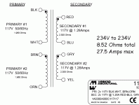
The 300VA 220V 1.36A, 6% regulation: https://www.hammfg.com/files/parts/pdf/1182M110.pdf
Primaries both are 1.960 ohm ±20% each
Secondaries both are 2.160 ohm ±20% each
The 300VA 220V 1.36A, 6% regulation: https://www.hammfg.com/files/parts/pdf/1182M110.pdf
Primaries both are 1.960 ohm ±20% each
Secondaries both are 2.160 ohm ±20% each
Last edited:
They've changed the style of data sheet, I did find them, squirrelled here in the electrical data panel:
The 300VA 220V 1.36A, 6% regulation: https://www.hammfg.com/files/parts/pdf/1182M110.pdf
Primaries both are 1.960 ohm ±20% each
Secondaries both are 2.160 ohm ±20% each
I've fed those into the LT Spice model. It shows 300W and just under 1.11A ac but low secondary voltage at full load on the secondary with a +20dB transient. So I'll revisit the inrush calculations tomorrow as it's late. In short with the bridge capacitive load I'm expecting from the remodelling:
220Vac rms secondary => 1.414*220 = 311Vdc peak
1.36Aac secondary => 0.62*1.36 = 840mAdc
I've seen the current calculations being more drastic - ie 4x required, so my concern is that this may still not be enough current.
I've also increased the local caps for the filtering but reduced the res cap from 6mF to 1.5mF. The result is showing about -91bB 100Hz spike. Will have to look at this again once the transformer is sorted.
I'd highly recommend doing a PSUD2 simulation as well as an LTSpice effort. PSUD2 provides a very quick way to alter parts and see the result of key design values on the secondary side of a power transformer, and is somewhat bullet-proof as a simulation goes, so makes a good backup for comparing results. Simulation always includes a risk of setup errors, and part model limitations.
Those PT winding resistances indicate the secondary winding would need an IEC 2A T fuse to survive the inrush charging of 6mF.
How long is the +20dB transient such that it sags the B+ voltage significantly ?
Those PT winding resistances indicate the secondary winding would need an IEC 2A T fuse to survive the inrush charging of 6mF.
How long is the +20dB transient such that it sags the B+ voltage significantly ?
I'd highly recommend doing a PSUD2 simulation as well as an LTSpice effort. PSUD2 provides a very quick way to alter parts and see the result of key design values on the secondary side of a power transformer, and is somewhat bullet-proof as a simulation goes, so makes a good backup for comparing results. Simulation always includes a risk of setup errors, and part model limitations.
Those PT winding resistances indicate the secondary winding would need an IEC 2A T fuse to survive the inrush charging of 6mF.
How long is the +20dB transient such that it sags the B+ voltage significantly ?
I’ll get it setup on PSUD2 but I’ll need to run it under Wine tomorrow.
They've changed the style of data sheet, I did find them, ....The 300VA 220V 1.36A, 6% regulation....
If you have that data you do not need anyting else to put a reasonable upper limit on current.
If 1.36A makes 6% or 0.06 sag, then 100% sag is 1.36A/0.06 or 22.7A. RMS; peak will be higher.
I agree about PSUD being a great tool but last night I was getting 57A peaks with an absurd-HUGE capacitor. When you get to absurd values it spins a wheel. (Change file extension back.)
Attachments
Ok I see you have a OSX version 😀 After a few checks I've installed it - let's see what comes up 🙂
With 220ohm:
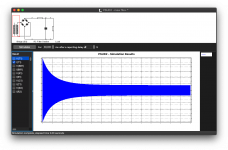
Only issue on the OSX version is there's no values marked (I suspect that it's because I'm running dark mode).
However this aligns with what I've seen with inrush management on LTSpice, this also matches given a 5ohm gives this:
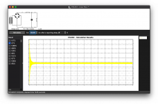
It also throws it's toys out the pram indicating 6+Amps current draw on the primary - which is precisely the inrush issue!
This is a high accuracy LTspice sim (ie alternate solver etc), first 30seconds are not recorded but then showing the next 30 seconds of stable run. This is running the full amp with left channel input 3.16V at 10Khz and the right channel with a 3.16V 30Hz. This takes a while (several hours) and about 100GB of diskspace:
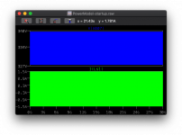
This is showing that the B+ match and the secondary current is a little higher. (using the 1.5mF res cap and 300uF caps to replace the 200uF in the design reducing the hum to -90dB in the output).
Switched the desktop to auto colouring, gives me the values:
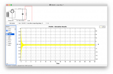
With 220ohm:

Only issue on the OSX version is there's no values marked (I suspect that it's because I'm running dark mode).
However this aligns with what I've seen with inrush management on LTSpice, this also matches given a 5ohm gives this:

It also throws it's toys out the pram indicating 6+Amps current draw on the primary - which is precisely the inrush issue!
This is a high accuracy LTspice sim (ie alternate solver etc), first 30seconds are not recorded but then showing the next 30 seconds of stable run. This is running the full amp with left channel input 3.16V at 10Khz and the right channel with a 3.16V 30Hz. This takes a while (several hours) and about 100GB of diskspace:

This is showing that the B+ match and the secondary current is a little higher. (using the 1.5mF res cap and 300uF caps to replace the 200uF in the design reducing the hum to -90dB in the output).
Switched the desktop to auto colouring, gives me the values:

Last edited:
On the passive filters I'm using some pretty brutal orders:
Res - 20Hz using 5.1R + 1500uF giving -17dB at 100Hz
Output stage uses a 0.5Hz using 1K + 300uF + 1K bidirectional LPF giving -40dB at 50Hz.
Input stage uses a 2.2K + 150uF, again giving -40dBish at 50Hz.
Looking at the current across the resistors that res has the biggest impact on the secondary current requirement.
I've adjusted the output, see if I can run 500R with 750uF. I think the issue is the LPF are simply burning off current in the resistors, hence the extra demand. Targeting the output stage LPF resistors should drop the wattage of heat at the cost of extra capacitance charge at the start - given I'm modelling 3.16V (ie +20dB) and this is sustained transient (the transformer model doesn't have a limiter to model sag and the current source model in LTSpice is a little 'hack' which can magic energy from nowhere if you're not careful).
- Home
- Amplifiers
- Power Supplies
- Anyone used a CPLD to manage inrush?
