hi there,
i'm contemplating modding an audio recording unit that i have.
in the input section it uses NJM2115 op amps. from what i've read so far online i think an OPA2134 will work well as a replacement, but i'm not experienced in this regard so i'm looking for advice and help as to not ruin my unit (if i can avoid it).
basically looking to open up the sound of it a bit.
the output stages use the NJM4580 [2 kinds (i think) labeled 2215U and 2218 U] and again from what i've read, either the AD8066 or the OPA2227 or OPA2228.
any experienced feedback would be appreciated, including advice for replacing the op amps as i have never done it before though i have moderate experience with electronics and a decent handle on soldering.
thanks
Hi. NJM2115 is optimised for low supply voltage of 5v and works down to 2Volts supply, possibly using single ended supply rather than dual + & - . You might have problems swapping this one. The 4580 is more conventional, but think you need to find out what supplies your unit runs on. Is it a DAT recorder ? Also what package are they, DIP8 , or surface mount.
Regards Karl
Regards Karl
thank you Karl,
the unit is a MOTU 828 mkII firewire recording unit.
I'm not 100% sure on the power or how to discern it rightly. haven't pulled out the multimeter to take measurements yet... not sure how to discern otherwise the voltage to these op amps. that being said, there is writing by the transformers indicating 3.3v. and looking at a few other parts some are rated at 6v max, i'm lead to believe that 3.3v is the voltage for the entire board save the 48v transformer that i assume is dedicated to the 48v phantom power supply for the two microphone inputs.
as for mounting, both the NJM4580's and the NJM2115's are surface mounted 8 pin units.
from what i can discern, the 2115's are the input op amps and the 4580's are the output op amps.
any guidance or input is appreciated.
thank you,
adam
Measure from signal ground to pin 8 of opamp (positive supply) and pin 4 (negative supply) . If your not sure just measure across pins 4 and 8 to get the total supply. If it's low you might be best leaving well alone, those OpAmps are optimised for use at low voltages.
Regards Karl
Regards Karl
Hello again,
thank you for the guidance Karl.
I took some measurements - both units just because - and here they are. They seem a bit high for the NJM2115 compared to its data sheet parameters, but this is what I measured:
*for signal ground, by the way, I plugged a TRS cable into an input at the back and used the sleeve as signal ground. I assume that's correct.
NJM2115
16.63v from terminal 4 to 8
10.61v signal ground to terminal 8
-5.9v signal ground to terminal 4
NJM4580
21.1v from terminal 4 to 8
10.7v signal ground to 8
10.0v signal ground to 4
Adam
correction on that last measurement for the 4580. signal ground to terminal 4 is -10.0v, not positive of course.
adam
adam
hey all,
did more research - it looks to me like the THS4032 would be a very good replacement for the NJM2115 in this situation. looks like there's enough voltage (requires minimum 4.5v+-) and the pin layout is the same.
can anyone tell me if this is one will likely work or not?
would it also work as a replacement for the NJM4580?
any thoughts are welcome.
thanks,
adam
Hi , The THS4032 is a very fast OpAmp and may not be stable in your application particularly if used at unity gain. You need to see circuit to see how they are configured. Also current consumption is much higher, important on battery powered equipment. Sorry to sound a bit negative, but I think you might end up worse off on this one. Those supply voltages are fine for most OpAmps, even the unbalanced one. Have you ever unsoldered surface mount components by the way ?
Regards Karl
Regards Karl
Hey Karl,
thank you again. That's helpful information.
I have not soldered or un-soldered surface mount components before. My understanding is that i need to be sure that: 1) I do not use too much heat (which will fry the op amps), 2) the old solder is well removed (perhaps with solder vacuum, perhaps braid), 3) to use only high quality silver solder and 4) to 'tin' the contacts on both sides before joining them. Anything else?
The unit is not battery powered - it runs on AC (switchable from 100-240v) with its own transformers (one for the circuit board and one for the phantom power for the microphones).
So my questions then are:
1) Is there harm in trying (ie soldering in and running some tests) the THS4032 to see if it will work by trial and error?
2) Any other good OP AMP recommendations?
3) Any other suggestions or tips regarding unsoldering and soldering surface mount components?
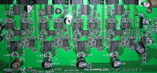
I'll send along a jpg of the section of the board that i'm looking at.
thank you again. That's helpful information.
I have not soldered or un-soldered surface mount components before. My understanding is that i need to be sure that: 1) I do not use too much heat (which will fry the op amps), 2) the old solder is well removed (perhaps with solder vacuum, perhaps braid), 3) to use only high quality silver solder and 4) to 'tin' the contacts on both sides before joining them. Anything else?
The unit is not battery powered - it runs on AC (switchable from 100-240v) with its own transformers (one for the circuit board and one for the phantom power for the microphones).
So my questions then are:
1) Is there harm in trying (ie soldering in and running some tests) the THS4032 to see if it will work by trial and error?
2) Any other good OP AMP recommendations?
3) Any other suggestions or tips regarding unsoldering and soldering surface mount components?
I'll send along a jpg of the section of the board that i'm looking at.
Hi, Would suggest you get hold of any old (scrap) pcb with surface mount components to practice on. The following works well and in the days before hi-tech desoldering stations, I used this technique all the time. I even bet an equipment sales rep I could unsolder a large surface mount I/C quicker than he could on his desoldering station. Now this takes practice, and you need a good iron, temperature controlled if possible, set to around 350 degrees C. Fit a medium sized bit, load the bit with solder and apply to new clean braid laid across the I/C pins. The "wicking action" will remove most of the solder but not all. Next using a jewellers screwdriver (you will have to experiment to find the right size) apply between each leg of the I/C and quickly apply clean soldering iron bit, not to the pin you are levering on but the PCB print just in front of it. The pin should lift free, and if your careful and just break the bond without damaging the pin or the print, the I/C should come cleanly off. I say cleanly, in fact most I/C,s are glued as well, so be sure that each pin is free and VERY gently prise off PCB. With the I/C off, again use braid to clean the print. Be careful, those fine tracks can easily be damaged or lift. Clean the board with a cotton bud and iso. It should look like new PCB. With practice you should be able to remove I/C so cleanly it is reusable with no physical damage to the pins. Sorry if that make anyone cringe but it can be got down to a fine art. Oh and I won the bet 😀
Any other good Op-Amp, well the OPA2604 does it for me, I think available in surface mount package.
Regards Karl
Any other good Op-Amp, well the OPA2604 does it for me, I think available in surface mount package.
Regards Karl
he he, so much for machines!
thank you so much, that's really helpful.
I think i'm off to my local computer recycler for some scrap boards.
I think I may also get some samples of the THS4032 just to see how/if it works - but i'll likely end up going with your OPA suggestion, it is also well spoken of.
thank you so much for your advice Karl.
Cheers and all the best to you.
Adam
hey there,
Karl, i don't know if you'll look again at this thread or not. But if you do or if someone else has some input, here goes.
the opa2604 is available as soic-8 which is not technically the same as the format for the NJM2115 (in this situation) which is a proprietary shape used only by that manufacturer (for the most part), or at least that's what i've gathered so far.
however, SOIC-8 has the same footprint as far as connections go. So they are usually interchangeable. so that's that.
i also had a thought - the application of the njm2115 is input, before the ADC - not output. the input dba level is always set at either +4db (with a 4db pad) or -10db (with a 10db boost). so, the unit would never be at unity gain - or always, depending on how it's routed i guess.
the voltages didn't change at all when i changed the setting from +4db to -10db and i don't know if they should have or not.
so two questions are:
1) is it risky to the ADC converters to try a different op amp that may not be suitable (namely the THS4032)?
2) would the above info (about input level) make stability at unity gain a non-factor?
I've ordered a couple of different samples to try - the opa2227 and the ths4032.
oh yeah, also - in reading some more, it looks like (if you look at the picture above) the 3rd njm2115 is likely for the ground and then isn't as important to change as the other two. thoughts?
cheers,
adam
Hi, No risk at all to convertors and if not used at unity gain probably will be O.K. but as ALWAYS, can't say for sure without seeing circuit diagram. Even the PCB layout can cause stability problems (unlikely but it can happen), if you are using an unsuitable device.
Regards Karl
Regards Karl
thanks so much Karl,
Your time, advice and input are greatly appreciated and very helpful.
all the best to you,
adam
Your time, advice and input are greatly appreciated and very helpful.
all the best to you,
adam
sorry to resurrect ol thread
Sounds like you are doing the Black Lion Mod?
I just had my unit done by BLA.
I actually have a problem that I am not sure they did the work.
My ins and outs are 5532's. Mostly TI but there appear to be some non TI ones as well.
ps yeah I know its not very DIY to pay someone else to do your upgrades, but I am more confident soldering wires than PCBs.
re BLA mod
hey calaverasgrande,
yes, basically like the BLA mod.
i assume yours is a motu as well. if so, motu uses njm4580's(output) and njm2115's(input) stock. so if they're all 5532's now bla's done something methinks.
bla has been doing these mods for a few years now and are pretty good at it. so i figure they either have learned that a) the 5532 is the best overall replacement or b)there is negligible difference between that chip and more expensive ones (so why waste the money?).
i mean, the 5532 is less than $1 compared to $4-$11 for other chips - times about 50 chips in a unit it adds up.
thanks for the tip about the 5532's if that is what they use. i'll add those to my sample list.
cheers,
adam
yeah, it is super hard to read the writing on those chips. I took some high res photos. I'll see if I can post those later.
cool. hope you end up being happy with the mod. those that i've talked to that have had it done are very happy with it. everything has more depth and more focus. if you haven't bought it already, the word clock is also a mighty upgrade. they used to build it in, but now it's external. i don't know what clock they use, but i suspect it's either a kwak-clock or one of the other top DIY contenders. if you want you can also build your own clock to hook up to the bnc connectors on the back, it just gets a little tricky trying to get multiple clock speeds. there are schematics available for most of the top clocks out there for DIY. just search this site for word clocks or audio clocks and you'll find what you're looking for. it's a fun and pretty cheap DIY - about as easy as building your own 5 watt amp, but way better.
done, well at least half
just posting a follow up.
i did it finally. i ordered some samples from TI. the ths4032's, OPA2227's and OPA2132's.
i was mostly concerned with the main outputs and then the inputs of my unit as well as two mic pre's on the front of the unit.
i put the 4032's in place of the opamps for the main outs, the first 2 inputs, and one of the mic pres. i used the 2227's on four of the inputs and the other mic pre.
so far i haven't used the 2132's for anything.
holy cow, what an improvement. i didn't even have to A-B test to hear the difference i the outputs, it was obvious as soon as i plugged it back in. amazing. the THS4032's are quite clear, and don't seem to have too much of a distinctive character. they also sound good for the inputs.
the OPA2227's seem to sound more pleasing on the mic pre and the inputs. they color the sound a little bit, but in a nice way... kind of like analog.
not that the 4032 sounds bad, just a bit more open - unrefined as it were. perhaps it's more accurate, but in recording, accurate only goes so far; pleasant is better usually.
as far as stability goes, no change. all the inputs and outputs are totally solid. so i guess the rest of the circuitry holds its own in the motu. good stuff motu.
next go around i'll try the 2132's in the inputs, maybe as the other mic pre. also, i'll eventually try to change the outputs so i can have nice signal for outboard effects. if i end up having more time i might experiment with some of the other op amps that people seem to favor.
as well, there are opamps in the input section that i assume are for 'stereo' inputs (when you link two inputs as one stereo input) that i haven't changed. i could be wrong about them being for interleaved stereo; i haven't changed them yet, so i don't know if that will affect my mono input sound. it's already a lot better though.
i ended up getting my friend who's an electronics wiz to put them in for me. he did in a few minutes what would have taken me a few hours. but now that i've seen it done, i have confidence to do it on my own
thanks for the input and help again,
adam
- Status
- Not open for further replies.
- Home
- Design & Build
- Parts
- anyone suggest a good quality replacement for NJM2115 [3028U] OP AMP