this is strictly wide band analog with digital measurements added on screen, so you think the digital section clock is mixing at both front ends? do they have a test mode you can shut down the measurement system?
Analog needs no help from digital to break into oscillation. No, I don't think it has a thing to do with the digital displays.
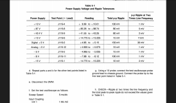
For reference checking out the PS:
Doc
Attachments
I appreciate the contact. I'm trying to take care of this on my own, just looking for a little advice. This was a working scope when my friend put it away 20yrs ago. Hoping someone has experienced the same symptoms.
Did you check the lithium battery?
Picking up a second scope in the morning to check the ripple currents, and a few film capacitors that I didn't replace on the power board. I'll let you know what I come up with.
I went through the service manual and set up the test scope to check ripple at the J119 header. As I said before, measuring voltage with the Fluke 87iii shows all within (near center) range. Now I don't have a ton of experience measuring ripple, so I'm not sure what it should look like. Pin 1 5v output shows a mess of spikes on my Tek 210, peak to peak varies from 4-10mv.
that was my 1st impression from your vid.
were all parts replaced with same values and otherwise identical in fitment, form, and function? It's usually a bad idea to do global parts exchange unless its a simple design. trouble shoot the original problem not shoot a shotgun full-o-parts. now you may have a different issue that's harder to locate.
All parts were replaced with exact values, only after testing and finding high esr or more than 30% out of spec. The majority of the larger caps had leaked all over the board. I didn't just throw a bunch of parts on it, even though the majority of repair sites suggested just that with this particular psu.
I went through the service manual and set up the test scope to check ripple at the J119 header. As I said before, measuring voltage with the Fluke 87iii shows all within (near center) range. Now I don't have a ton of experience measuring ripple, so I'm not sure what it should look like. Pin 1 5v output shows a mess of spikes on my Tek 210, peak to peak varies from 4-10mv.
You measure DC level with your DVM and see values nicely in spec. The spec table will specify acceptable ripple levels (for most supplies in low mv range) which are best measured with the oscilloscope in AC coupled mode on the lowest range (probably 5 mv/div). If the spec is 5 mv ripple P-P then the ripple line should all comfortably fit within one vertical division on the screen. I am working on a Tek 465 I recently acquired with vertical switching section issues. The scope is 40ish years old and looks not to have been previously touched (all original PS caps) and all of the PS voltages and ripple levels were well within spec.
My second scope is digital, with p-p readout. So it's normal for the ripple to look like static? The spec says within 10mv p-p, which it is. Another pin says 100mv p-p, and I'm only seeing 20mv p-p. I guess I'm having trouble understanding what I'm looking at. Showing my ignorance. I've accomplished a lot without a scope, but as I get deeper into other repairs I'm seeing one as a necessity.
1) for linear supplies look at 120 Hz ripple ( adjust time base and trigger )
2) for switchers (SMPS) look at both line ripple (above) AND 2x switching frequencies. must exclude hash by selecting 20M BW limit and using HF probe jacks ( reduce probe ground loop area) and / or differential measurement. get both ripple measurements on different time base settings. BTW the common mode hash from SMPS spoils many folks ideas of ripple.
3) DUT circuit induced PS ripple may often be present! look for it
digital o-scopes can fool many looking at PS ripple ( because there often is many AC components present) its not simple.
*trouble shooting using an old analog scope and using trigger source to help identifying ripple sources and their components more quickly. you can see the whole bandwidth in real time!
Last edited:
I used #2 based on the service manual at 2mv/div. After researching some more, I understand now that I'm looking at the AC ripple from the DC supply. It looks as should be expected. This evening I'm going to begin working away from the power supply, as everything seems to be within spec now.
I'm a not so proud owner of a 2465 with the "blurry trace" issue on channels 1 and 2. 3 and 4 are relatively clean. I've been meaning to get on this but I got the unit cheap, replaced a shorted output rectifier in one of the supplies, and have been running ever since. It would be handy to fix this and then go through and align everything. I looked at the circuit once intending to make the repair but nothing jumped out as "I bet it's that!".
running inputs into X & Y channels would give clues. lets use more trouble shooting skills
I've connected my transistor checker (curve tracer) with the scope in xy with decent results. Only problem is when adjusting the volts/div to set the trace height/width, the trace will fade or disappear in some combinations.
The 2465 is on a bench that is under a tarp at the moment, but maybe tomorrow I could dig it out. Ever since plopping in the power diode that was ahead of the anode voltage circuit, I've had no problems with the display... just what appears to be noise in the vertical amps. If I use 20MHz band limit it does clean up quite a bit, but I know that's not fixing anything.
Sounds like we're facing the same issue. As many components as there are in these scopes, it's highly unlikely we'd find the same cause.
I'd bet 5 bucks the vertical "noise" is the same problem, and I'm sorta looking forward to working on it, but I have no idea what's up with your trace fade problem. Sometimes that can even be a triggering issue.
online block diagrams I can study up? > so it needs to use common chan 1 and 2 hardware/
can we limit it to vert amplifier problem since BW filter and attenuator are at the front end.
maybe inject AC coupled 20M-ish square waves at various stages and look at outputs.
can we limit it to vert amplifier problem since BW filter and attenuator are at the front end.
maybe inject AC coupled 20M-ish square waves at various stages and look at outputs.
I guess I'll look into the cleaning thing tomorrow. My suspicion that it had something to do with the hybrid amplifiers is the main reason why I didn't finish fixing the scope. I know those are hard to find in any sort of reliable condition, for whatever price. I made sure they were at least clean from a cooling perspective and moved on.
Far as drawings, I've located the CD I bought. I'm not sure I have legitimate copies myself but the outfit that sold them to me was at artekmedia.com. I have no leads on free information floating around.
Far as drawings, I've located the CD I bought. I'm not sure I have legitimate copies myself but the outfit that sold them to me was at artekmedia.com. I have no leads on free information floating around.
Far as drawings, I've located the CD I bought. I'm not sure I have legitimate copies myself but the outfit that sold them to me was at artekmedia.com. I have no leads on free information floating around.
http://bama.edebris.com/manuals/
"BAMA"=Boat Anchor Manual Archive. Have most Tek manuals for free download. Got both 2445 & 2465 manuals there.
Doc
I cleaned all of the hybrids and attenuators already with no changes. The contacts were dirty, but it didn't help much. I have a full service manual for both models, let me know if you have trouble finding one.
- Status
- Not open for further replies.
- Home
- Design & Build
- Equipment & Tools
- Anyone repair Tektronix 24xx Scopes?