Good idea onni and nice work as usual, speculate if lets lets say your latest edition that it have 60º dispersion could it then help up at 16kHz area make it a bit rectangular or elipse say 40x60º dispersion ?
In past have often thought about using one of Daytons cheap 10 or 8 inch waveguide, you know truncate it where diameter suits TC9/10F surround and fabricate a mounting part that is glued to the truncated waveguide. Think their 10 incher looks most smooth as seen below and if it have any interest i would gladly sponsor a 8 and 10 incher shipped to your private address for trials.
In past have often thought about using one of Daytons cheap 10 or 8 inch waveguide, you know truncate it where diameter suits TC9/10F surround and fabricate a mounting part that is glued to the truncated waveguide. Think their 10 incher looks most smooth as seen below and if it have any interest i would gladly sponsor a 8 and 10 incher shipped to your private address for trials.
Attachments
Member
Joined 2009
Paid Member
Byrtt - sounds interesting! .... The 8" would be my interest in terms of cabinet size but who knows if I'll ever get around to building...
Hi BYRTT!Good idea onni and nice work as usual, speculate if lets lets say your latest edition that it have 60º dispersion could it then help up at 16kHz area make it a bit rectangular or elipse say 40x60º dispersion ?
In past have often thought about using one of Daytons cheap 10 or 8 inch waveguide, you know truncate it where diameter suits TC9/10F surround and fabricate a mounting part that is glued to the truncated waveguide. Think their 10 incher looks most smooth as seen below and if it have any interest i would gladly sponsor a 8 and 10 incher shipped to your private address for trials.
I experimented some with a more narrow horn and found two decent results, one with 12 cm deep WG and one with 20 cm deep. I have not iterated very much and believe that the dip above 10 kHz is fixable.
12 cm deep, 19 cm wide WG


20 cm deep, 26 cm wide WG


I do think that some on-axis anomalies are inevitable when dealing with a waveguide for something larger than maybe 1.5". But that may be ok if rest of response looks ok, no?
I might actually take you up on that offer regarding the Dayton WG. Today I ordered a UMIK-1 (I've been borrowing from a neighbor I had) and my fingers are itching to make some sawdust.
/Anton
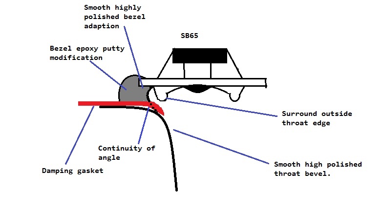
Did you get any caliper measurements of the 10F? Would be interesting to know if sims apply to that driver as well.Visually, the TC9 and 10F cone profile are very similar. Rounded dust cap in middle. Profile of cone is mostly conical, might be a bit curved. I can take some caliper measurements later when I get back to the lab. All you can do is assume pistonic for first cut. Make throat same dia as middle of surround roll and allow a smooth curved undercut below surround to bezel edge, Probably put dampening felt in that crevice. Here is the profile Bushemeister came up with after much trial-and-error:
http://www.diyaudio.com/forums/multi-way/285030-bookshelf-multi-source-horn-125.html#post4644522
/Anton
Caliper measurements of 10F? You mean mechanical dimensions? It follows the factor CAD drawing pretty well.
I was thinking of the cone profile, that's not available as CAD drawing right?Caliper measurements of 10F? You mean mechanical dimensions? It follows the factor CAD drawing pretty well.
/Anton
No, best way there is to cut a piece of paper to fit then scan that. I’ll try to do that but why do you need it? Unless building a phase plug?
I guess I misunderstood you in post #5. The profile is not only intersting for phase plug design, but also for waveguide design.No, best way there is to cut a piece of paper to fit then scan that. I’ll try to do that but why do you need it? Unless building a phase plug?
I don't need a full measurement of the profile, just check if the main measurements of the 10F are the same as for the TC9.
- Distance from faceplate to deepest point.
- Distance from faceplate to top of dustcap.
- Diameter of dustcap.
- Diameter of cone (top of surround to top of surround).
- Width of surround.
- Height of surround.
I'll post the measurements of the TC9 I took and anyone who has the 10F can compare.
/Anton
These are the values I've measured for the TC9:
- Distance from faceplate to deepest point: 11 mm
- Distance from faceplate to top of dustcap: 4.5 mm
- Diameter of dustcap: 24 mm
- Diameter of cone (top of surround to top of surround): 70 mm
- Width of surround: 6.5 mm
- Height of surround: 1.5 mm
The profile looks like this in the model:

/Anton
- Distance from faceplate to deepest point: 11 mm
- Distance from faceplate to top of dustcap: 4.5 mm
- Diameter of dustcap: 24 mm
- Diameter of cone (top of surround to top of surround): 70 mm
- Width of surround: 6.5 mm
- Height of surround: 1.5 mm
The profile looks like this in the model:
/Anton
First WG made
Alright, so I made a rough waveguide using XPS (from the lumber yard). First cut circular holes (60 mm diameter) in two 50 mm thick panels and glued them together. Then I traced the profile from a decent simulation (95 mm deep waveguide) on a paper.

Then I used a rasp to remove material, and controlling the result with the paper cutout.

It follows the profile with an accuracy of +-1.5 mm (yes, a little rough).
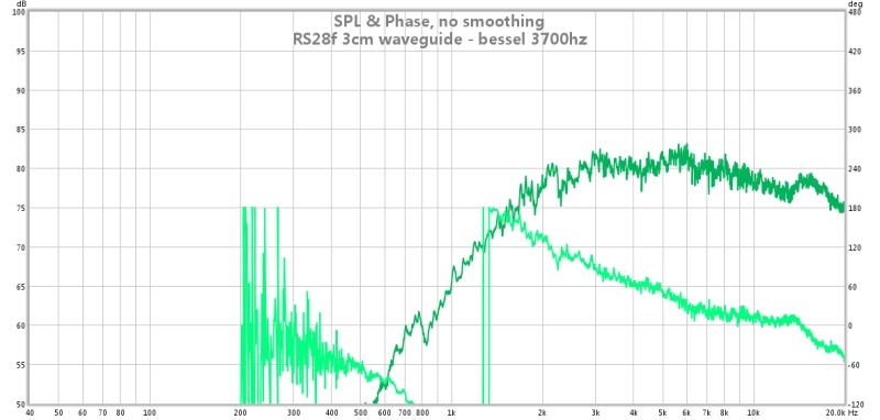
Response of speaker when laying flat on the ground (0, 30, 60 deg, 1 m):

And with WG (0, 30, 60 deg, 1 m):

Here is with WG when on a stool on a table (0, 30, 60, 90 deg, 1 m, ~1.5 m off ground):

No gating or smoothing.

PSY smoothing, no gating.

No smoothing, 5 cycle FDW (gating).

And finally, REW sim with a 1 PEQ applied (888 Hz, -13 dB, Q = 0.9).
/Anton
Alright, so I made a rough waveguide using XPS (from the lumber yard). First cut circular holes (60 mm diameter) in two 50 mm thick panels and glued them together. Then I traced the profile from a decent simulation (95 mm deep waveguide) on a paper.
Then I used a rasp to remove material, and controlling the result with the paper cutout.
It follows the profile with an accuracy of +-1.5 mm (yes, a little rough).
Response of speaker when laying flat on the ground (0, 30, 60 deg, 1 m):
And with WG (0, 30, 60 deg, 1 m):
Here is with WG when on a stool on a table (0, 30, 60, 90 deg, 1 m, ~1.5 m off ground):
No gating or smoothing.
PSY smoothing, no gating.
No smoothing, 5 cycle FDW (gating).
And finally, REW sim with a 1 PEQ applied (888 Hz, -13 dB, Q = 0.9).
/Anton
I did also measure at 0.5 m distance (when elevated on a stool on a table). Looks like this with PSY smoothing:

And predicted response with HP (minidsp, 2nd order Q = 0.71) at 1600 Hz:

Looks like it could cross over to a woofer around 700-750 Hz. I'd like to get this below 500 Hz, maybe a 15 cm deep waveguide will do.
/Anton
And predicted response with HP (minidsp, 2nd order Q = 0.71) at 1600 Hz:
Looks like it could cross over to a woofer around 700-750 Hz. I'd like to get this below 500 Hz, maybe a 15 cm deep waveguide will do.
/Anton
Nice work. That must have created a blue dust storm 🙂
The sensitivity looks about the same in both cases. Could you post distortion measurements for both.
The sensitivity looks about the same in both cases. Could you post distortion measurements for both.
Nice work, Onni. Member Jeshi also made waveguides from EVA foam sheets glued together. They sanded very nicely with course sandpaper. No rough bits left.
EVA foam for performance speaker enclosures

EVA foam for performance speaker enclosures
Not so bad as the rasp was quite rough and there was no wind. But I did use a vacuum cleaner to collect the dust to avoid having a blue back yard 🙂Nice work. That must have created a blue dust storm 🙂
The sensitivity looks about the same in both cases. Could you post distortion measurements for both.
The WG increases the sensitivity between 300 Hz and 2 kHz as seen below (measured on ground):

This is distortion measurement for the case without WG:

And this is with WG when EQd flat (auto minidsp):

There is also a HP at 250 Hz (I think). I just set it at a value that made the distortion reasonably flat. Looks good with WG, except peak at 2.5 kHz. Third harmonic between 700 and 1000 Hz is also a little high. But when I look at the non-EQs measurement done on a table these peaks don't exist:

Note that the measurements were done outdoor with birds, airplanes, neighbours building porches etc. Maybe that's what is causing the peaks?
/Anton
Thanks @onni for adding those graphs. I was interested in comparing your waveguide results to an experiment I was doing. It was trying to get better midrange perf (higher sensitivity, lower distortion) from a PC83-3. Links to 2 horn shapes I tried.
Le Cléac'h : Dayton PC83-8 (3") test results
Tractrix : Dayton PC83-8 (3") test results
Le Cléac'h : Dayton PC83-8 (3") test results
Tractrix : Dayton PC83-8 (3") test results
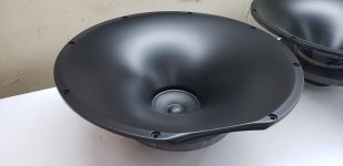
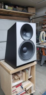
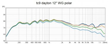
I truncated a now discontinued 12" version of the Dayton waveguide and made an adapter ring for the TC9. Polar measurements are at 1m 0, 5, 15, 30, and 45 deg.Good idea onni and nice work as usual, speculate if lets lets say your latest edition that it have 60º dispersion could it then help up at 16kHz area make it a bit rectangular or elipse say 40x60º dispersion ?
In past have often thought about using one of Daytons cheap 10 or 8 inch waveguide, you know truncate it where diameter suits TC9/10F surround and fabricate a mounting part that is glued to the truncated waveguide. Think their 10 incher looks most smooth as seen below and if it have any interest i would gladly sponsor a 8 and 10 incher shipped to your private address for trials.
Attachments


Distortion 0deg @ 1m.

Louder.

At a louder volume I noticed a resonant buzz at 200hz. I have to track it down.
Louder.
At a louder volume I noticed a resonant buzz at 200hz. I have to track it down.
Last edited:

Nice work, thanks for sharing!Maybe a more meaningful polar measurement.
View attachment 1014742
Is that the raw response?
/Anton
- Home
- Loudspeakers
- Full Range
- Anyone made a waveguide for the TC9 (or 10F)?