Brian, I have no proper tools to measure noise, so I can not comment.
The control processor really expects to see a verification of the bus voltage, with disconnected amp section once I got more than 90V out of the supply.
I've tried the amp with 4 12VSLA, it really works great.
I'm trying to direct couple to a digital crossover, but sadly the crossover internal format is 24 bit left alligned, while the TAS chip has only 16 bit left alligned format. I have to convert to i2s, posibly can do it during the weekend...
Is there any detailed info available about the Equibit coding.
I'm (was?) a big fan of no oversampling dacs, but this "power DAC" with it's built in oversampling filter seems to be a better compromise, than a DAC plus an analog amp in my case.
Service manual XR25/45
HI
Has any of you guys obtaied the service manual - i have so not been able to obtain it in Europe so far.
BTW is the US version of the XR25/45 also capabel of 230 Volts AC input ?
Any pointers to the differneces between 25 and 45 would also be much appreciated - besides the differneces in DIgital input where the 45 supports 192 Kb/s
Thanks
Morten
adding digital Xover in front of digital amps for each speaker
My new sound card has digital outputs for 5.1 HT.
How about adding a 2 way digital crossover in front of the TI stereo digital amp chip? Putting the Xover and amplifier at each speaker would allow customization for each speaker and allow digital cables between source and HT speakers. A 2-way Xover would cover 2-way speakers, as well as 3-way deisgns by using passive components between the midrange and tweeter.
If anyone is building PCBs for the TI digital amplifier, please consider adding the DSPs necessary for a FIR filter crossover?
Re: adding digital Xover in front of digital amps for each speaker
Do you mean 3 sets of spdif outputs? What card is that?
There are some SHARC modules available from Danville (www.danvillesignal.com) that might be suitable for doing a crossover directly in front of the amp, but they are a bit light on detail on their web site. They aren't bargain-basement, but they're not bad (start at $400 or so), but you'd have to do the I/O card on top of that.
For a 2-way system you could probably manage around 1024 tap FIR filters if I'm reading the SHARC data sheet correctly. This isn't too bad, but might be a bit short. Certainly more than enough for carefully designed IIR/hybrid xovers though.
LineSource said:My new sound card has digital outputs for 5.1 HT.
Do you mean 3 sets of spdif outputs? What card is that?
There are some SHARC modules available from Danville (www.danvillesignal.com) that might be suitable for doing a crossover directly in front of the amp, but they are a bit light on detail on their web site. They aren't bargain-basement, but they're not bad (start at $400 or so), but you'd have to do the I/O card on top of that.
For a 2-way system you could probably manage around 1024 tap FIR filters if I'm reading the SHARC data sheet correctly. This isn't too bad, but might be a bit short. Certainly more than enough for carefully designed IIR/hybrid xovers though.
Just gonna throw this back up to the top of the list here. Wanted to see if there was an update on how things were going with it.
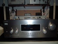
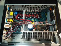
Finally I was able to complete the one box crossiver/room corrector/5ch amp project based on the Pana receiver and a pro digit crossover.
The crossover and amp is in one 1U high 19" rack box now with direct i2s interface.The box has only digital I/O and speaker outputs. Configuration is done via an RS232 coupled computer GUI. The amp output sections are 4*12V SLA battery powered.
A couple of remarks:
To use the amp from SA-SX10 standalone with external bridge power it is enough to supply the following signals:
1. <digital_in> MCLK (256fs)
2. <digital_in> SCLK (64fs)
3. <digital_in> LRCLK (fs)
4. DGND
5. <digital_in> FRONT DATA (I2S 24bit data)
6. <digital_in> SURROUND DATA (I2S 24bit data)
7. <digital_in> CENTER / SUB DATA (I2S 24bit data)
11. <digital_in> DOUBLE SPEED (for audio data rate) (0: fs = 44.1KHz or 48KHz, 1: fs = 88.2KHz or 96KHz)
15. <analog_in> AMP RESET +5V
17. <digital_in> /MUTE – HeadPhones (must be tied to +3.3V)
21. 12V_GND (DGND)
22. +B (12V)
23. 12V_GND (DGND)
24. +B (12V)
Note that the /MUTE – HeadPhones input has no internal pullup, leaving it unconnected will disable the speaker outputs. Other MUTE inputs has internal pullups, can be left unconnected and the channel will be enabled.
18. <digital_in> /MUTE – Front (0: Front speakers disabled, 1: Enabled)
19. <digital_in> /MUTE – Center & Surround (0: Center and surround speakers disabled, 1: Enabled)
20. <digital_in> /MUTE – Subwoofer (0: Subwoofer line out disabled, 1: Enabled)
The power supply for the output section can be disconnected and the bridge outputs can be directly fed from batteries. It is really efficient, can drive my speakers at full volume for several days.
One interesting thing: I always wondered why Panasonic decided to change the power supply voltage in the -20 - -40dB range for volume control.
Now, feeding the amp with a controlled digital signal it seems the the SA-XR receivers has greater than 1 gain combined with a kind of soft limiter in the 0 - -20dB range. It seems they decided that nobody will use this range regularly, only when the input volume is low.
Gain 1 seems to be at around -18db volume setting. Pushing the Panasonic receiver with high level input signal and closer to 0db volume setting will result digital limiting and clipping, maybe the reason for reported harshness at high volume.
fcserei - very cool, thanks for the info.
Couple questions, of course 🙂
How are you doing volume control? Are you using the control portion of the XR-10 at all for this, or did you just pull the power amp sections and do volume conventionally ahead of the xover?
What size batteries are you running? Have you tried lower rail voltages? I was thinking that 24V might be adequate, but don't know how the amp would react to this; two big batteries for 24v would be cheaper/easier than 4 smaller ones for 48V. Any suggestions on chargers?
Of course now that I think about it, 4 cells that could be configured as 12, 24 or 48 V would be the most flexible, and would emulate the variable supply topology. Have you done enough listening to eval how much degradation in amp performance there is with reduced-resolution input?
Nice!fcserei said:Finally I was able to complete the one box crossiver/room corrector/5ch amp project based on the Pana receiver and a pro digit crossover.
The crossover and amp is in one 1U high 19" rack box now with direct i2s interface.The box has only digital I/O and speaker outputs. Configuration is done via an RS232 coupled computer GUI. The amp output sections are 4*12V SLA battery powered.
A couple of questions:
- What is the AmpHour rating of the batteries you're using?
- Which digital crossover did you start with?
- Any comments on the sound?
Of course!One interesting thing: I always wondered why Panasonic decided to change the power supply voltage in the -20 - -40dB range for volume control.
Now, feeding the amp with a controlled digital signal it seems the the SA-XR receivers has greater than 1 gain combined with a kind of soft limiter in the 0 - -20dB range. It seems they decided that nobody will use this range regularly, only when the input volume is low.
I'm kicking myself for assuming that the dB values displayed were accurate.
When I was playing around with the amp board outside of the receiver, I still was using the receiver as my I2S source.
This makes a lot more sense now.
Perhaps the gain and compression above displayed -20dB could be considered a digital implementation of allowing the user to 'Turn it to eleven'.😀
Compression certainly could be part of it, but...Gain 1 seems to be at around -18db volume setting. Pushing the Panasonic receiver with high level input signal and closer to 0db volume setting will result digital limiting and clipping, maybe the reason for reported harshness at high volume.
I still have the observation that the original switcher power supply was slewing around at higher volumes. I found that replacing this supply with LA batteries made the supply nice and stiff. This was accompanied by a very substantial improvement in sound quality.
Are you using MLS measurements for room correction?
I'm still quite a bit away from being able to try this. It would be interesting to hear about your experiments.
Regards,
Brian.

dwk123 said:
How are you doing volume control? Are you using the control portion of the XR-10 at all for this, or did you just pull the power amp sections and do volume conventionally ahead of the xover?
I've removed the power amp board and put it in an 1U box together with the DSP. I'm not using any other part of the receiver now. Volume control is in the DSP digitally, but I use rather power supply voltage switching. The DSP is freely configurable, it can have volume control either before or after crossover. It can also have different output dither for different volume settings.
What size batteries are you running? Have you tried lower rail voltages? I was thinking that 24V might be adequate, but don't know how the amp would react to this; two big batteries for 24v would be cheaper/easier than 4 smaller ones for 48V. Any suggestions on chargers?
I'm running the amp on four 7Ah SLA. The volume is quite matched to my room and tastes, means 0dB volume at 48V is about just the right loudness, not party level, but quite enoug for classical. Switching to 2 (24V) or 1 (12V) batteries I have a cheap way of limited volume control.
I just charge the batteries with cheap chargers when the amp is not in use.
Of course now that I think about it, 4 cells that could be configured as 12, 24 or 48 V would be the most flexible, and would emulate the variable supply topology. Have you done enough listening to eval how much degradation in amp performance there is with reduced-resolution input?
I can't hear any degradation with dropping the voltage, and I don't need big adjustment range in the digital domain as I almost always listen at arond 0dB level.
fcserei said:
I've removed the power amp board and put it in an 1U box together with the DSP. I'm not using any other part of the receiver now.
That's what I thought, but wanted to be sure. I had a similar idea when I saw a local place with very cheap 2U rackmount cases.
I'm running the amp on four 7Ah SLA. The volume is quite matched to my room and tastes, means 0dB volume at 48V is about just the right loudness, not party level, but quite enoug for classical. Switching to 2 (24V) or 1 (12V) batteries I have a cheap way of limited volume control.
I just charge the batteries with cheap chargers when the amp is not in use.
Wow - a total of only 28Ah? Thats much less than I would have expected. I forget exactly what I was looking at, but I was thinking along the lines of 2x 80Ah. Sounds like that might be unnecessary.
How many channels are you using - all 5 or only 4?
One thing I did realize in my battery thoughts is that there shouldn't be much difference in battery life due to the voltage used. ie 28Ah should last about the same regardless of whether you use it as 4-in-series for 48V or in parallel for 12 - it will all depend on the power output used. This is very different from Class A/B topologies where the wasted power increases with increasing voltage, since output current will be constant.
I can't hear any degradation with dropping the voltage, and I don't need big adjustment range in the digital domain as I almost always listen at arond 0dB level.
Assuming you're right about the 0dB level being around -20 on the volume dial, I can see this working. I usually listen around -30 or so and so *might* get away with 24V, but maybe not - there might not be much headroom.
dwk123 said:
Wow - a total of only 28Ah? Thats much less than I would have expected. I forget exactly what I was looking at, but I was thinking along the lines of 2x 80Ah. Sounds like that might be unnecessary.
Yeah, they are really efficient. One charge last about a week listening, couple of hours a day.
How many channels are you using - all 5 or only 4?
4 channels, 2 almost full range and 2 below 45Hz.
Assuming you're right about the 0dB level being around -20 on the volume dial, I can see this working. I usually listen around -30 or so and so *might* get away with 24V, but maybe not - there might not be much headroom.
I had no time to verify, but I'd rather say somewhere between -12 - -18dB. One day I'll feed the i2s from the Pana directly to the crossover and can tell exactly.
I've tried 6V supply, and it worked great with high efficiency speakers - 2A3 tubes be afraid 😀
Supply Levels and Batteries
The following relationship applies when using the power supply voltage for volume control:
Vcontrol=Vorig*2^([dB change]/6)
For example, for an original supply voltage of 42V, to get a -5dB adjustment:
42V*2^([-5dB]/6dB)=23.7V
Here's a chart showing the relationship for the SA-XR10, which has a max supply voltage of 42.2V:
(The 65% wattage adjustment factor is an approximation for max output duty cycle and output losses.)
Supply 42.2V
Load resistance 8ohms
..................................................65%factor
dB......Vsup.......Wp..........Wrms......Wrms
0........42.2........222.6......157.4......102.3
-1.......37.6........176.7......124.9......81.2
-2.......33.5........140.2......99.2........64.5
-3.......29.8........111.3......78.7........51.2
-4.......26.6........88.3........62.5........40.6
-5.......23.7........70.1........49.6........32.2
-6.......21.1........55.7........39.4........25.6
-7.......18.8........44.2........31.2........20.3
-8.......16.7........35.1........24.8........16.1
-9.......14.9........27.8........19.7........12.8
-10.....13.3........22.1........15.6........10.2
-11.....11.8........17.5........12.4........8.1
-12.....10.6........13.9........9.8..........6.4
-13.....9.4..........11.0........7.8..........5.1
-14.....8.4..........8.8..........6.2..........4.0
-15.....7.5..........7.0..........4.9..........3.2
-16.....6.6..........5.5..........3.9..........2.5
-17.....5.9..........4.4..........3.1..........2.0
-18.....5.3..........3.5..........2.5..........1.6
-19.....4.7..........2.8..........2.0..........1.3
-20.....4.2..........2.2..........1.5..........1.0
Here's what I actually measured on the SA-XR10:
(It matches the above calculations pretty well)
0dB 42.2V
-1dB 37.6V
-2dB 33.5V
-3dB 29.8V
-4dB 26.6V
-5dB 23.7V
-6dB 21.1V
-7dB 18.8V
-8dB 16.8V
-9dB 15.0V
-10dB 13.4V
-11dB 11.7V
-12dB 10.6V
-13dB 9.5V
-14dB 8.5V
-15dB 7.6V
-16dB 6.8V
-17dB 6.1V
-18dB 5.4V
-19dB 4.8V
-20dB 4.3V
Here's another chart showing a 48V supply (which is right at the rating limits of the parts):
Supply 48.0V
Load resistance 8ohms
..................................................65%factor
dB......Vsup.......Wp..........Wrms......Wrms
0........48.0........288.0......203.6......132.4
-1.......42.8........228.6......161.6......105.1
-2.......38.1........181.4......128.3......83.4
-3.......33.9........144.0......101.8......66.2
-4.......30.2........114.3......80.8........52.5
-5.......26.9........90.7........64.1........41.7
-6.......24.0........72.0........50.9........33.1
-7.......21.4........57.1........40.4........26.3
-8.......19.0........45.4........32.1........20.8
-9.......17.0........36.0........25.5........16.5
-10.....15.1........28.6........20.2........13.1
-11.....13.5........22.7........16.0........10.4
-12.....12.0........18.0........12.7........8.3
-13.....10.7........14.3........10.1........6.6
-14.....9.5..........11.3........8.0..........5.2
-15.....8.5..........9.0..........6.4..........4.1
-16.....7.6..........7.1..........5.1..........3.3
-17.....6.7..........5.7..........4.0..........2.6
-18.....6.0..........4.5..........3.2..........2.1
-19.....5.3..........3.6..........2.5..........1.6
-20.....4.8..........2.8..........2.0..........1.3
-21.....4.2..........2.3..........1.6..........1.0
(Note that only about 1dB additional volume is obtained by the extra six volts)
Using switched 12V batteries would give the following:
48V.......0dB
36V.......~-3dB
24V.......-6dB
12V.......12dB
******************
One of the concerns I had about using unregulated batteries for the output bridge supply was regarding a possible decrease in volume over time. Starting with 48V, the above chart shows that the voltage has to drop a full five volts before a 1dB decrease occurs. With 7Ah batteries, an amp could operate for just over an hour at maximum continuous power (one channel) before a 1dB drop occurred. Music statistically doesn't exceed 1/8 of full power. With this consideration, the amp could output full volume for over six hours before a 1dB drop occurred.
A 12V nominal SLA battery typically has about a 13V initial voltage. Within about a minute, at light to moderate loads, the voltage will drop to about 12V. Once this first drop occurs, the voltage will remain within a couple of tenths of volts for quite a long time, even with drastically changing loads. As long as there is sufficient capacitance in parallel with the battery, any of this voltage variation will occur at subsonic frequencies, and will only cause a small fraction of a dB in amplitude variation.
Once I realized the above I decided to abandon attempting electronic supply regulation.
I think this is a beautiful example of a brute force design. An SLA battery and parallel capacitor is an extremely stiff supply over the audio bandwidth. This is just what an open loop switched output section of a digital amp needs. Better still, the high efficiency of the switched output makes batteries a practical consideration.
******************
A final concern is the potential for crosstalk or other channel interaction when powering more than one channel from the same battery. Careful layout and decoupling could avoid this. Of course, using separate sets of batteries for each channel completely avoids this issue.
SLA battery pricing is somewhat proportional to the number of amp-hours you are buying. Because of this, I think it makes sense to buy separate batteries for each channel. (i.e. more smaller batteries vs. fewer larger ones.)
******************
A couple of implementation issues:
Directly connecting a battery to a parallel capacitance causes a very large in-rush current. Worst case, this can cause a capacitor to explode. Even if the capacitors survive the in-rush, they will be degraded over time.
One easy solution is to put a series power resistor between the battery and capacitor. Once the cap has been precharged through the resistor, a relay can be used to short out the resistor and directly connect the cap to the battery.
With a little more work, the precharge circuit could also provide a means to switch in a battery charger when the amp wasn't being used.
Regards,
Brian.
Re: Supply Levels and Batteries
It is more like 10 hours for 4 channel for me, but my speakers are relatively light loads in the midband, and the sub channels rarely go above -30dB. The average level of classical music is also lower. With continuous recharging every day it is not a problem for me.
None of them seems to has any audible effect in the current layout. I also could not measure any effect of it but my measurement tools are very limited.
Brian Brown said:
With this consideration, the amp could output full volume for over six hours before a 1dB drop occurred.
It is more like 10 hours for 4 channel for me, but my speakers are relatively light loads in the midband, and the sub channels rarely go above -30dB. The average level of classical music is also lower. With continuous recharging every day it is not a problem for me.
As long as there is sufficient capacitance in parallel with the battery, any of this voltage variation will occur at subsonic frequencies, and will only cause a small fraction of a dB in amplitude variation.
.
.
A final concern is the potential for crosstalk or other channel interaction when powering more than one channel from the same battery.
None of them seems to has any audible effect in the current layout. I also could not measure any effect of it but my measurement tools are very limited.


This thread has been dormant for a while - I hope that means everyone is busy with their projects, not that they've gone idle.
I have some 12V batteries on the way to experiment with battery power on my two Panasonic Equibit units - the direct digital interface experiments are on hold for a while.
I was browsing the TI site again in preparation for this, and saw that there is a new multi-channel modulator out (or one I hadn't been aware of) - the 5076. The very cool thing for the DIY-er is that the EVM (using the 5182 and providing 6-channels @100W) appears to be directly orderable from the TI website.
The EVM looks to be perfect for experimentation, and they claim a measured performance of 105dB S/N on the two main channels from the evm board (102 for the other 4 channels). It appears that there is a serial port and associated PC software for config etc. including tweaking the output bridge timing params which appears to be critical to realizing the potential of the chips.
At $500 it looks pretty good to me. If I weren't between jobs at the moment, I'd order one immediately.
Link:
http://focus.ti.com/docs/toolsw/folders/print/tas5076-5182c6evm.html
Yep... Still busy...
I've been looking at that new EVM as well.
The one thing that I've always been disappointed with TI's digital amp EVMs is that they don't include a reference power supply, one of the biggest quality variables.
They've mentioned a couple of power supply application notes:
SLEA027:
Power supply recommendations for DVD receivers.
"Gives basic requirements and guidelines for selecting the optimal power supply for a non-feedback digital amplifier used in a DVD receiver."
SLEA028:
Power supply requirements for AV receivers.
"Describes power supply and system considerations when designing Class BD-mode amplifier without feedback, for example a system with TAS5076/5182 used in AV receivers."
I've been very interested in reading these, but they're still not available.
I'm still using the SA-XR10 Equibit board while I work on other parts of the project.
The SA-XR25 / SA-XR45 use TAS5036 / TAS5182 chipsets. I don't have one of these receivers, but I've reviewed their schematics. The SA-XR25 is less than half the cost of TI's development board. The TAS5076 appears to be pin compatible with the TAS5036. Hacking into one of these receivers might be something to consider as an alternative.
The new six channel TAS5076 modulator chip looks very interesting. It appears to have better specs than all but the TAS5015 (which doesn't have an internal PLL). Previously the TAS5012 had the 2nd best specs.
The TAS5015 / TAS5012 use external capacitors to set the H-bridge deadtime. The TAS5076 has a digital adjustment (ABD Delay parameter). I like the idea of being able to easily tweak this value. This could be especially useful when matching the amp to a specific speaker driver. The ABD Delay parameter could be tweaked for minimum distortion using MLS measurements.
The TAS5076 has an interchannel delay parameter so that the switching of the six different H-Bridge channels can be offset from each other. This improves performance when operating from a single supply by preventing crosstalk at switching frequencies. (It still doesn't prevent supply crosstalk from occuring at audio frequencies.) If separate supplies are used, then this feature isn't important.
The other feature the TAS5076 has that the TAS5015 / TAS5012 don't is programmable correction for DC offset due to asymmetry in the output stage. I'm taking a wild guess that this may be the main reason the TAS5076 has better specs than the TAS5012.
In the meantime I'm still plugging on a multiple TAS3013 processor board. Hopefully it won't be too much longer...
Regards,
Brian.
I’ve been evaluating digital modulators from Zetex, TI & Sony. All have been externally Re-latched using an external low phase clock circuit.
Here’s a brief round up of the results, all Dynamic Range results are Awtd and are about –2dB worse then optimal due to poor phase noise of the LVDS RX / TX used on the common Eval board.
THD @ 0dB 997Hz measured differentially, IMD results are the 3rd order products (18KHz & 21KHZ) of the stimuli tones at 19KHz & 20KHz @ –6dB each: -
NFM = Noise Floor modulation
Zetex 1MHz HPWM, DR = 118dB, IMD –63dB! NFM Greater then 10dB! THD 0.0019%
Zetex 2MHz HPWM, DR= >124dB, IMD –85dB, NFM Less then 10dB, THD 0.00050%
Sony CXD9634 / M65817AFP, DR=116.7dB, IMD –95dB, NFM Less then 1dB, THD 0.00037%
TI TAS5015 DR=114.7dB, IMD –115dB, NFM Less then 1dB, THD 0.00020%
The Zetex has very poor Noise Floor Modulation & IMD results @ 1MHz.
The Sony’s a good all round modulator, having a SRC & gain control, and good stop band rejection.
The TI has brilliant IMD & good THD results, but poorer stop band rejection, with no Gain or SRC. I’m very impressed with this modulator – as it only operates at ~ 384KHz PWMFs (x8 Fs)
Both the Sony and the TI sound VERY good – without an external SRC, the Sony beats the TI, although the TI beats the Sony when it’s combined with a good SRC (the SRC side-steps the TI’s Stop Band image problems).
For some FFT plots of the TI, see my posting “Wanted circuit for Low Phase Noise 100MHz clock”
- Status
- Not open for further replies.
- Home
- Amplifiers
- Class D
- Anyone interested in a digital amplifier project?