Ill let you guys carry on with this thread, its all well above my head now LOL
Except finger damage, been there recently, caught my little finger in a knotty wheel in an angle grinder, wasnt nice! Hope your hand heals up soon.
Except finger damage, been there recently, caught my little finger in a knotty wheel in an angle grinder, wasnt nice! Hope your hand heals up soon.
Thanks for the well-wishes, and very sorry if I contributed to the misdirection of your thread. Please don't let me run you off! If you have lingering questions, bring us all back to whatever would be helpful to you.
Few
Few
How low can your ESL go?
OK This thread is becoming very interesting guys, and I'd like to thank all you folks for throwing your bits into this conversation. Cal, I think I'd like to talk about integration between panel and bass unit for a few, if you care to do sohttp://www.diyaudio.com/forums/images/smilies/biggrin.gif
I understand that the difference between lower FR and upper FR for a bass unit is a world apart. so what then do you do when the ESL is supposed to handle... say 125 hz-175hz...how does a panel react when frequencies like that are introduced? Does it distort the other higher frequencies?
Thanks, Steve
Hi,
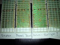
To me the CSD of the Aerius looks unusually severe ragged.
I´m quite sure it has nothing to do of which material the stator is made. If it had, the degree of openess must correlate with the CSD plot. The less open the more ´reflections´ the worse the CSD. With the distances involved (less than 10mm even for a double reflection!) artefacts stemming from reflections between the stators should only be visible at very high frequencies but not as low as in the ML´s plot. The rather less open Quads proove the opposite and I know of my panels that show much less CSD artefacts too.
I can think of several reasons of such a behaviour. Dimensions of the panel, or more precise dimensions of each segment of the panel. Materials used for construction. Evenness of the diaphragm coating and latst but not least the measurement setup itself. Anyway the performance of the Aerius is under par CSD-wise.
@wayne
I think we stop dicuss here. Get the basics straight. I won´t argue with You about what´s been proven in practise and can be read in any good textbook. And that differs clearly from Your theory.
@Few
get well soon mate
jauu
Calvin
Few: Sorry about the finger mate , geez and on New years eve @ that ... 🙁
Calvin : I think our focus should be more with the poor CSD plots and the interpretation of such than micro focusing on stator gap for the answer. 🙄
The quad is not less open than the rest and in saying so , you have missed my point entirely, i said Open panel (Baffle presence ) they also use PVC , have smaller segmented panels which are flat vs curved and they sound much better naked . For me a wired flat stator sounds much better than a perf curved panel, would be interesting to compare CSD plots .
Anyway my apologies for bringing this up for discussion , I will study more books , get the basics straight regardless of what the CSD plots reinforces 🙂
Happy New Year Gentlemen and may the panel gods move us ahead for 2010
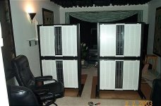
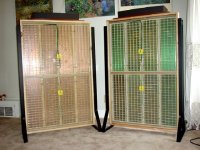
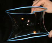
Attachments
Last edited:
Hi,
I interpreted it as Your explanation for the hash. So could You explain what You meant with ´early reflections´, closed curved stator´, ´more open wire stator´ and ´holey´?
Openeness as I understand it is the relation between the two parts of areas of the membrane which are ´shaded/covered´ by the stator and those which are ´not shaded/covered´ by the stator. Typically the openess is less than 50%. Around 40% seems to be the usual compromise. Audiostatic uses some more, Quads use something below 40%. That´s why I would call the Quad´s ´closed´. But I´ve seen no measurement yet, that correlates CSD and openness of a panel. If it would the effect should only show at very high frequencies.
The Aerius´s raggedness in the CSD plot starts in the midrange. The reason for this must be different from its ´stator openness´.
@liquisonic
You may read http://www.diyaudio.com/forums/planars-exotics/64620-ping-calvin.html
The response curves in here are typical response curves of hybrid panels. Fullrangers extend to lower frequencies and feature a more pronounced dip around 200Hz but the curves apply basically to FRs too.
Now with all ESLs one of the major design goals is efficiency. It is the higher the smaller the diaphram-stator distance (d/s) can be made. To provide for the membrane not to be drawn into the stator, the freely vibrating area is therefore reduced and the mechanical tension of the membrane is made high (high resonance frequency). Especially the latter point hinders low crossover frequencies since You should avoid driving a panel close to its resonance frequency unless You need to do so because you design a FR-Panel.
The suggested 125Hz-175Hz is a very difficult frequency range to cross over, since it is just the point where You might need to decide about which death to die. Either way slightly off of the optimum and the result is reduced dyanamic range and/or reduced sonic quality. Above the mentioned freq-range things are much easier (with regard to design and electronics) and below that range already construction principles of a FR-type apply and limit. Over the years I tried to reduce the crossover frequency from ~300Hz to now ~170Hz, because sonics improved. But while the d/s remained the same the size of the panel doubled from 3000cm² to 6000cm². While such large panels can offer incredible realistic sound they need to be placed in very large rooms and listened too with several m of listening distance.
Besides the efficiency problem allmost all panels (regardless of flat or curved type) exhibit a strong increase in distortion values below 200Hz (see the Quad´s curves as example). Above 200Hz a well designed panel exhibits exceptional low values of distortion even under large signal conditions. Below 200Hz and all the glory is gone. That is the frequency range dynamic drivers are superior to ESLs in many aspects.
It is my experience that 200Hz -30Hz/+100Hz, depending on panel size, is the crossover frequency range which offers the optimum for hybrid ESLs.
Crossing over at even higher frequencies and alot of what defines the ´magic´ of ESL-sound is lost.
jauu
Calvin
well, than I must hav misinterpreted the above cite completely.The Hash is bad due to the early reflections from using a closed curved stator as opposed to a more open wired stator . I had discussed this in the past with those that favor "holey " stators
I interpreted it as Your explanation for the hash. So could You explain what You meant with ´early reflections´, closed curved stator´, ´more open wire stator´ and ´holey´?
Openeness as I understand it is the relation between the two parts of areas of the membrane which are ´shaded/covered´ by the stator and those which are ´not shaded/covered´ by the stator. Typically the openess is less than 50%. Around 40% seems to be the usual compromise. Audiostatic uses some more, Quads use something below 40%. That´s why I would call the Quad´s ´closed´. But I´ve seen no measurement yet, that correlates CSD and openness of a panel. If it would the effect should only show at very high frequencies.
The Aerius´s raggedness in the CSD plot starts in the midrange. The reason for this must be different from its ´stator openness´.
@liquisonic
You may read http://www.diyaudio.com/forums/planars-exotics/64620-ping-calvin.html
The response curves in here are typical response curves of hybrid panels. Fullrangers extend to lower frequencies and feature a more pronounced dip around 200Hz but the curves apply basically to FRs too.
Now with all ESLs one of the major design goals is efficiency. It is the higher the smaller the diaphram-stator distance (d/s) can be made. To provide for the membrane not to be drawn into the stator, the freely vibrating area is therefore reduced and the mechanical tension of the membrane is made high (high resonance frequency). Especially the latter point hinders low crossover frequencies since You should avoid driving a panel close to its resonance frequency unless You need to do so because you design a FR-Panel.
The suggested 125Hz-175Hz is a very difficult frequency range to cross over, since it is just the point where You might need to decide about which death to die. Either way slightly off of the optimum and the result is reduced dyanamic range and/or reduced sonic quality. Above the mentioned freq-range things are much easier (with regard to design and electronics) and below that range already construction principles of a FR-type apply and limit. Over the years I tried to reduce the crossover frequency from ~300Hz to now ~170Hz, because sonics improved. But while the d/s remained the same the size of the panel doubled from 3000cm² to 6000cm². While such large panels can offer incredible realistic sound they need to be placed in very large rooms and listened too with several m of listening distance.
Besides the efficiency problem allmost all panels (regardless of flat or curved type) exhibit a strong increase in distortion values below 200Hz (see the Quad´s curves as example). Above 200Hz a well designed panel exhibits exceptional low values of distortion even under large signal conditions. Below 200Hz and all the glory is gone. That is the frequency range dynamic drivers are superior to ESLs in many aspects.
It is my experience that 200Hz -30Hz/+100Hz, depending on panel size, is the crossover frequency range which offers the optimum for hybrid ESLs.
Crossing over at even higher frequencies and alot of what defines the ´magic´ of ESL-sound is lost.
jauu
Calvin
I would like to add that Sanders' book wasn't much help to me in finding a suitable step up transformer when I built my ESL's. Of course, I might have gotten more from Sanders' information if I were more knowledgeable about electronics but dummies like myself need a bit more help. Anyway, I would like to repost one of my thread on that subject here:
http://www.diyaudio.com/forums/newreply.php?do=newreply&p=2035324
http://www.diyaudio.com/forums/newreply.php?do=newreply&p=2035324
Interest thread. So from what i gather most of the curved panels only curve to around 30 degrees. Would it make more sense to curve a panel further to give better off axis response? Also some of you advocate wire stators surely a curved wire would be the best of both worlds?
oublie,
e.g. ML panels have curved panels less than 30 °, its about 20°
The more you bend the stator the more problems occur with asymmetric force (Front-rear-stator) and mechanical stability of the membrane.
Curved panels are very tricky to design and more tricky to produce.
Capaciti
e.g. ML panels have curved panels less than 30 °, its about 20°
The more you bend the stator the more problems occur with asymmetric force (Front-rear-stator) and mechanical stability of the membrane.
Curved panels are very tricky to design and more tricky to produce.
Capaciti
oublie,
e.g. ML panels have curved panels less than 30 °, its about 20°
The more you bend the stator the more problems occur with asymmetric force (Front-rear-stator) and mechanical stability of the membrane.
Curved panels are very tricky to design and more tricky to produce.
Capaciti
So hows about a multiple panel one with say 3 independant 20° stators with as narrow an edge as mechanically viable. This would eliminate any stability issues as for asymmetric force is this really a big issue?
of course a wired panel would elimiate any major mechanical issues apart from the fact that the diaphram can only be stretched in the vertical plane.
oublie,
ever heard about the venetian blind effect ?
This happens to flat panels which are arranged in angles adjecent to each other
Capaciti
ever heard about the venetian blind effect ?
This happens to flat panels which are arranged in angles adjecent to each other
Capaciti
oublie,
ever heard about the venetian blind effect ?
This happens to flat panels which are arranged in angles adjecent to each other
Capaciti
Good point, comb filtering at high frequencies caused by gap between transducers.
Would this be as big an issue off axis? Theres always going to be some comb filtering even at very high frequencies due to the spacing of esl wires or the distance between holes although this is not going to be an issue with less than 1 cm hole to hole centre spacing. Not only this but surely the effect caused by having stator bracing every 20cm or so would have as much effect?
Do not forget catenary line...oublie,
e.g. ML panels have curved panels less than 30 °, its about 20°
The more you bend the stator the more problems occur with asymmetric force (Front-rear-stator) and mechanical stability of the membrane.
Curved panels are very tricky to design and more tricky to produce.
Capaciti
Do not forget catenary line...
I'm guessing you mean catenary line changes with the force applied by the stator and bias voltage causing a variation in the diaphram to spacer distance in a curved panel? (maths isn't really my thing i'm afraid) surely this is normal no matter what the curvature?
or do you mean make the curvature the same as the catenary line for the diaphram width under no tension?
Last edited:
What I meant is a complex task as compared with flat surface membrane. See attachment. Even more complex: having tube sector instead of complete tube stretched.I'm guessing you mean catenary line changes with the force applied by the stator and bias voltage causing a variation in the diaphram to spacer distance in a curved panel? (maths isn't really my thing i'm afraid) surely this is normal no matter what the curvature?
or do you mean make the curvature the same as the catenary line for the diaphram width under no tension?
To Capacity: is the mechanical stability of a curved membrane any better?
Alex
Attachments
Hi,
the mechanical stability of the membrane is not better, but the mechanical stability of the stators.
jauu
Calvin
the mechanical stability of the membrane is not better, but the mechanical stability of the stators.
jauu
Calvin
Yeah, I built what is essentially a Sanders amp about 32 years ago after the magazine artlcles appeared. Once I demo'd it for the Toronto hi-fi establishment. The difference between matching tranfs. and direct high voltage (2400 volt B+ on the tubes) is far more than MC versus MM cartridges. Or the difference between tap water and a new Brita filter.
Just a bit daft to drive ESLs with matching transformers, eh.
I used it to run Dayton-Wrights, 140-3500 Hz.
Not for the faint of heart or those with small kids.
I'm back to the matching transformers but I can remember the sound.
Just a bit daft to drive ESLs with matching transformers, eh.
I used it to run Dayton-Wrights, 140-3500 Hz.
Not for the faint of heart or those with small kids.
I'm back to the matching transformers but I can remember the sound.
- Status
- Not open for further replies.
- Home
- Loudspeakers
- Planars & Exotics
- Anyone built roger sanders designs?