Charlie, I live in Statesboro, can you in any way help me with making something like you posted? I have 2 Adcom amps one adcom preamp( with issues) but I really like the driver at the floor and the angle for dispersion acroos the tall cabinet. You may even know our store. Audio Dynamic in Statesboro, I have been there for allmost nine years, untill I had a ATV crash(never ride those again) however, please if you dont mind, post or private message me, remember VT? Rick Zettweeeer something, Brian Shaw, Virtual Technologies car sub boxes? I know both still to this day, Rick is working in Savannah, Les moved to Tennasee, i think i spelled that wrong. Either way, it is nice to know someone close here, you might know Kenny Shpeard, has a thing for 350Z's. I did all of his custom work for him. PM ,me, mavric, or Nathan
Charlie, I live in Statesboro, can you in any way help me with making something like you posted?
There are a lot of great ESL's in this forum; no doubt some sound better than mine and most would be easier to build, but I am pleased to offer any assistance. You're only 45 miles from me so why not grab your favorite cd's and drop by my place for a listening session first? Will PM you my phone number and directions.
Hi,
@a.wayne: post #16
I don´t get what You mean. With a dipole there´s basically the driver behaving as a dampened mass-spring system. A CB adds spring force and reduces damping (higher fb and Qtb). BR and TML add a second mass-spring system, typically one with low damping (high Q-value of the BR-port). Bandpasses add even more mass-spring sytems.
In filter theory the pure dynamic speaker can be viewed in a simplified way as a highpass filter of 2nd order (12dB/oct). Dipole beeing the same, as well as the closed box (both systems only modify the values of spring force, mass and damping).
BR can be viewed as an Highpass of 4th order (24dB/oct) and Bandpasses can be of even higher order. In the way the filter order rises, the group delay rises.
Dipoles starting at app 6ms, CBs ~8-12ms, the rest mostly >20ms. Sonically values >10ms become audible. Sound gets a boomy character.
The question is rather, how behave/interact those coupled mass-spring systems than how ´big´ the spring is or how much effective mass is involved. Cone flexing and breakup hardly play amy role in pure bass applications.
btw. the Youtube video is pure advertisement. As one knows ads tell us alot but seldomly the truth.
@Liquisonic
the dipole has the problem of efficiency. It requires much more membrane area than other principles. Besides getting very sizy the bass still lacks a bit of ´power´ in the lowest register, especially when the larger the listening room is.
You can solve the problem with a CB subwoofer which is crossed over at very low frequencies, if possible below the lowest room mode, so that it doesn´t exite any room modes but just ´pressurizes´ the room. The dipole providing for the mid-to upper bass doesn´t need to be so big anymore and the CB subwoofer can be comparably small. This concept has been adopted by ML´s Statement II which I still regard as a masterpiece of conceptual stringence and beauty. My own large ESLs are concepted very similar and those surely can rock. Effortless dynamics like a large horn system, but without the many flaws of horns is the result.
@graeme uk:
tubes are highvoltage-highimpedance devices, ESLs are highvoltage-highimpedance loads. So by their very nature they should match well. But if the amp doesn´t fit the load powerwise or with regard to stabilty it will sound bad, regardless of it beeing made of tubes or solidstate devices.
The larger the panel and the larger the stator-stator distance of the panel the more power is needed to drive the it. A small 15W amp might be sufficient only for a mid-sized to small hybrid panel.
The drive problem is not solved by just the ´right´ transformer. If the amp doesn´t supply sufficient output voltage (runs into clipping) a higher transforming audio-tranny might help. But this reduces the load impedance the amp sees. So the current demands rise and the amp may run into current clipping now. There´s no way around an amplifier having enough power. You can fudge a bit with the voltage and current needs of the panel, but not with its power demands.
jauu
Calvin
@a.wayne: post #16
Which of the above alignment do you think stores the most energy .. has the biggest spring , has the most effective Mass and suffers the most from cone breakup and flexing ....
Hmmm could it be the one that is a monopole requiring considerable force just to move it's diaphragm while trying to imitate a dipole..
I don´t get what You mean. With a dipole there´s basically the driver behaving as a dampened mass-spring system. A CB adds spring force and reduces damping (higher fb and Qtb). BR and TML add a second mass-spring system, typically one with low damping (high Q-value of the BR-port). Bandpasses add even more mass-spring sytems.
In filter theory the pure dynamic speaker can be viewed in a simplified way as a highpass filter of 2nd order (12dB/oct). Dipole beeing the same, as well as the closed box (both systems only modify the values of spring force, mass and damping).
BR can be viewed as an Highpass of 4th order (24dB/oct) and Bandpasses can be of even higher order. In the way the filter order rises, the group delay rises.
Dipoles starting at app 6ms, CBs ~8-12ms, the rest mostly >20ms. Sonically values >10ms become audible. Sound gets a boomy character.
The question is rather, how behave/interact those coupled mass-spring systems than how ´big´ the spring is or how much effective mass is involved. Cone flexing and breakup hardly play amy role in pure bass applications.
btw. the Youtube video is pure advertisement. As one knows ads tell us alot but seldomly the truth.
@Liquisonic
the dipole has the problem of efficiency. It requires much more membrane area than other principles. Besides getting very sizy the bass still lacks a bit of ´power´ in the lowest register, especially when the larger the listening room is.
You can solve the problem with a CB subwoofer which is crossed over at very low frequencies, if possible below the lowest room mode, so that it doesn´t exite any room modes but just ´pressurizes´ the room. The dipole providing for the mid-to upper bass doesn´t need to be so big anymore and the CB subwoofer can be comparably small. This concept has been adopted by ML´s Statement II which I still regard as a masterpiece of conceptual stringence and beauty. My own large ESLs are concepted very similar and those surely can rock. Effortless dynamics like a large horn system, but without the many flaws of horns is the result.
@graeme uk:
tubes are highvoltage-highimpedance devices, ESLs are highvoltage-highimpedance loads. So by their very nature they should match well. But if the amp doesn´t fit the load powerwise or with regard to stabilty it will sound bad, regardless of it beeing made of tubes or solidstate devices.
The larger the panel and the larger the stator-stator distance of the panel the more power is needed to drive the it. A small 15W amp might be sufficient only for a mid-sized to small hybrid panel.
The drive problem is not solved by just the ´right´ transformer. If the amp doesn´t supply sufficient output voltage (runs into clipping) a higher transforming audio-tranny might help. But this reduces the load impedance the amp sees. So the current demands rise and the amp may run into current clipping now. There´s no way around an amplifier having enough power. You can fudge a bit with the voltage and current needs of the panel, but not with its power demands.
jauu
Calvin
Last edited:
Thanks.
It seems, at the moment i dont have the funds for the required amp AND the esl's.
No point having esl's if i cant drive them.
So, for now i think ill stick with my tannoys, build a new amp and re-visit esl's at a later date.
At least i understand the requirements now 🙂
It seems, at the moment i dont have the funds for the required amp AND the esl's.
No point having esl's if i cant drive them.
So, for now i think ill stick with my tannoys, build a new amp and re-visit esl's at a later date.
At least i understand the requirements now 🙂
curved panels are quite beamy. The dispersion is very good as long your offset angle corresponds to the curvature of the panels. if you further increase the measurement angle, a significant drop of level is the result.
Thats why ML speakers have a small sweet spot within +/- 10 to +/-15 degrees. If you sit more off-centered, you will recognize a significant "breakdown" of the stage.
Hi Capaciti,
This is indeed what one would expect given the geometry of the device. I found some measurements on the Martin Logan Aerius, that (fig. 7) does not look very pretty indeed. Then again we all know how hard it is to do good measurements on big panel speakers... I suppose the primary reason to do a curved panel is to improve dispersion but that does not seem to happen except for a small angle.
I did a couple of simulations and found that with proper segmentation we can get a rather nice controlled directivity pattern, but I'm still looking for the optimum configuration (whatever that may be).
Hi,
@a.wayne: post #16
I don´t get what You mean. With a dipole there´s basically the driver behaving as a dampened mass-spring system. A CB adds spring force and reduces damping (higher fb and Qtb). BR and TML add a second mass-spring system, typically one with low damping (high Q-value of the BR-port). Bandpasses add even more mass-spring sytems.
In filter theory the pure dynamic speaker can be viewed in a simplified way as a highpass filter of 2nd order (12dB/oct). Dipole beeing the same, as well as the closed box (both systems only modify the values of spring force, mass and damping).
BR can be viewed as an Highpass of 4th order (24dB/oct) and Bandpasses can be of even higher order. In the way the filter order rises, the group delay rises.
Dipoles starting at app 6ms, CBs ~8-12ms, the rest mostly >20ms. Sonically values >10ms become audible. Sound gets a boomy character.
The question is rather, how behave/interact those coupled mass-spring systems than how ´big´ the spring is or how much effective mass is involved. Cone flexing and breakup hardly play amy role in pure bass applications.
jauu
Calvin
Hello Calvin ,
We will have to agree to disagree 🙂
I would agree that TL and BP speakers are not ideal for this application and would favor CB over those arrangements. In regards to ML speakers , well less say ML's panel/Bass combination is like water and Oil , they don't mix 2 well ....😛
Disagree that a CB is the way to go over a BR. There is just no way IMO for a Sealed Box to mate cohesively with a Dipole panel operating below 500 hz . The radiating patterns ( polar response) completely throws it out of the picture for me .
BR with proper time alignment will be the most cohesive with any dipole panel and Boomy Bass is not exclusive to BR speakers , i have heard many CB speakers that don't get it right and have to revert to EQ for a decent sound /response . A good BR will not have a " boomy sound " and if done right will have similar bass characteristics of an OB with better efficiency and control.
Of course , the proof is always in the pudding and i would gladly give any curve panel , CB hybrid ESL a listen ......
Regards ,

Last edited:
Hi,
a CB behaves like a monopole eventually going into beaming at higher frequencies. A BR behaves like a monopole going into beaming at higher frequencies. They behave absolutely the same way in the frequency range of crossover. The reasons of a monopolar distributing bass not integrating well with a panel are totally due to the distribution character and the crossover flanks beeing asymmetric (the latter is especially the case with older MLs with a -6dB bass flank and someting around -36dB for the panel). The same two reasons apply for BR. Replacing the CB by a BR doesn´t improve things (the CB Sequel2 was clearly better performing than the BR Sequel1) with regard to radiation pattern.
A BR does not necessarily sound boomy, as a CB doesn´t necessarily sound tight. But comparing decently constructed designs a CB will alweays sound cleaner and more precise...point. Its more difficult to find an BR-alignment that sounds precise and doesn´t boom. The common practise to squeeze every Hz out of a small driver leads to such boom boxes. As long as You stay below a Qtb of ~1 a CB is fully OK.
To this another factor adds. A BR tends to ´overpower´ the room. Below the lowest room mode there´s an increase in sound pressure level that is countered by the decrease that a CB exhibits below its resonance frequency. The result is a linear in-room response. With the BR´s extended response to lower frequencies a increase in in-room response results. BR tend to build up a ´bass-pressure´ that simply is not contained in natural music.
In short, BR is not for music but for fun. 😀😀
@AJ
Dispersion of a curved panel is not as wide in reality as it is claimed to be.
But its enough to release You from nailing Your head to a fixed spot as is needed with an unsegmented flat panel. 😉
If You have to have Your head fixed within less than +-1° to avoid differences of up top 10dB in amplitude response I regard such a speaker as totally impractical.
jauu
Calvin
Hi Calvin,
I'm sorry for my ignorance. But what do you mean by BR? I suppose CB stands for closed box. Isn't it?
Wachara C.
I'm sorry for my ignorance. But what do you mean by BR? I suppose CB stands for closed box. Isn't it?
Wachara C.
Closed box + esl = yuck!
There are so many points/opinions on this thread that I am only going to say a few things here...
First, I'll have to agree with a wayne that matching a cb with an esl is the worst I've ever heard, indeed... oil and water! lol
A tl is the least expensive/space conserving way to "match" an esl with something that doesn't stick out like a sore thumb imho, and if I did have the $,and the space I'd opt for something like the DBA (double bass array) {look it up on AVS Forum}.
I see lots of people using an IB for bass that is "non-resonant", and that to me is the goal in matching up an ESL with some sort of "supporting bass" as any dipole including ESLs is surface area dependent. Am I making sense here?
Calvin, I looked up Manger in my perusing of this thread, and find it to be very interesting .
Enough rambling for now, but I would certainly like to keep this discussion going, and not to let it die, as I find ESLs (and other "effortless" sounding transducers VERY interesting indeed)
BTW BR = bass reflex right?
Steve
P. S. please "call" me on anything that is factually incorrect
Hi,
BR= BassReflex, or maybe Bottom Rumble? 😛
@Liquisonic
I disagree. The question is where do CB and BR(or a TML) behave differently and where do they behave equally. The amplitude response of the resonator of a BR or TML shows bandpass character with an upper bandwidth limit of around 100Hz-150Hz. In the frequency range above all 3 bass principles behave the same, ie. like a CB. They underly the same principles and weaknesses with regard to crossoverss and integrating problems to a panel. Since You can´t change the distribution character (they will be monopoles, whatever may come) good or bad integration is a matter of crossover construction.
Don´t mix up single listening experiences of supposedly bad examples of a principle with the basic principle itself.
Again, differences between CB and BR/TML are restricted to a frequency range well below the crossover frequency to the lowest octaves. With regard to building ease, and technical parameters CB is superior to BR and TML. And it is the most compact building principle and the cheapest too. BR and TML require more volume, more effort and more parts.
What You like to listen too...well that is a totally different piece of meat.
jauu
Calvin
I found some measurements on the Martin Logan Aerius, that (fig. 7) does not look very pretty indeed. Then again we all know how hard it is to do good measurements on big panel speakers...
I hope this isn't too much of a distraction from the original intent of this thread, but since the issue of measurements of large panel speakers came up I'd be curious about other people's opinions. Atkinson (JA) wrote the following in the "Measurements" section of the link arend-jan provided:
The high treble is similarly hashy, however, while the low- and mid-trebles feature a number of resonant ridges.
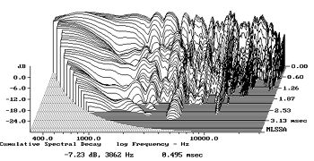
Fig.8 MartinLogan Aerius, cumulative spectral-decay plot at 45" (0.15ms risetime).
As I explain in the Quest Z review, this kind of waterfall behavior is typical of panel speakers in that a large, uniformly driven, low-mass diaphragm appears to exhibit chaotic behavior. While the diaphragm's average position responds uniformly to the driving force, there are small areas which move more than the average and others that move less. I believe that such behavior is often mistaken by audiophiles for "clarity," "fast transients," and "transparency." I also believe that it tends to accentuate/exaggerate detail by surrounding each transient edge of the music with a little halo of hash.
It strikes me that the explanation is quite a stretch given the information available in the measurement. How can you determine from the SPL at one point in front of a speaker that some areas are moving more and others less, and doing so chaotically? And a "halo of hash"?
My main question, though, is why it is that crappy looking cumulative spectral-decay plots often do seem to be associated with large panels that many listeners think have quite clear transients. Can anyone shed any light on this?
Few
The explanation given is indeed completely bogus especially the 'halo of hash' for each transient which simply does not happen. On the other hand this panel has some serious problems if you ask me, that waterfall plot looks plain ugly. I have never seen such bad performance for the panels that I have measured myself. So I don't think it's that typical at all.
Hi,
a CB behaves like a monopole eventually going into beaming at higher frequencies. A BR behaves like a monopole going into beaming at higher frequencies. They behave absolutely the same way in the frequency range of crossover. The reasons of a monopolar distributing bass not integrating well with a panel are totally due to the distribution character and the crossover flanks beeing asymmetric (the latter is especially the case with older MLs with a -6dB bass flank and someting around -36dB for the panel). The same two reasons apply for BR. Replacing the CB by a BR doesn´t improve things (the CB Sequel2 was clearly better performing than the BR Sequel1) with regard to radiation pattern.
A BR does not necessarily sound boomy, as a CB doesn´t necessarily sound tight. But comparing decently constructed designs a CB will alweays sound cleaner and more precise...point. Its more difficult to find an BR-alignment that sounds precise and doesn´t boom. The common practise to squeeze every Hz out of a small driver leads to such boom boxes. As long as You stay below a Qtb of ~1 a CB is fully OK.
To this another factor adds. A BR tends to ´overpower´ the room. Below the lowest room mode there´s an increase in sound pressure level that is countered by the decrease that a CB exhibits below its resonance frequency. The result is a linear in-room response. With the BR´s extended response to lower frequencies a increase in in-room response results. BR tend to build up a ´bass-pressure´ that simply is not contained in natural music.
In short, BR is not for music but for fun. 😀😀
@AJ
Dispersion of a curved panel is not as wide in reality as it is claimed to be.
But its enough to release You from nailing Your head to a fixed spot as is needed with an unsegmented flat panel. 😉
If You have to have Your head fixed within less than +-1° to avoid differences of up top 10dB in amplitude response I regard such a speaker as totally impractical.
jauu
Calvin
Hello Calvin ,
CB = Crappy Bass
BR= Bass respectable ..... 😀
Now Calvin , place the Ports in the rear of the enclosure ...don't look so monopole now does it ... What about the port frequency , something about it being out of phase .. Hmmm 😀
There are so many points/opinions on this thread that I am only going to say a few things here...
First, I'll have to agree with a wayne that matching a cb with an esl is the worst I've ever heard, indeed... oil and water! lol
A tl is the least expensive/space conserving way to "match" an esl with something that doesn't stick out like a sore thumb imho, and if I did have the $,and the space I'd opt for something like the DBA (double bass array) {look it up on AVS Forum}.
I see lots of people using an IB for bass that is "non-resonant", and that to me is the goal in matching up an ESL with some sort of "supporting bass" as any dipole including ESLs is surface area dependent. Am I making sense here?
Calvin's CB works , he uses Synthetic oil ....... 😀
I hope this isn't too much of a distraction from the original intent of this thread, but since the issue of measurements of large panel speakers came up I'd be curious about other people's opinions. Atkinson (JA) wrote the following in the "Measurements" section of the link arend-jan provided:
It strikes me that the explanation is quite a stretch given the information available in the measurement. How can you determine from the SPL at one point in front of a speaker that some areas are moving more and others less, and doing so chaotically? And a "halo of hash"?
My main question, though, is why it is that crappy looking cumulative spectral-decay plots often do seem to be associated with large panels that many listeners think have quite clear transients. Can anyone shed any light on this?
Few
See if you can find the one he did on a Quad speaker , I'm sure it was cleaner than that . The Hash is bad due to the early reflections from using a closed curved stator as opposed to a more open wired stator .
I had discussed this in the past with those that favor "holey " stators 😀
Last edited:
See if you can find the one he did on a Quad speaker , I'm sure it was cleaner than that . The Hash is bad due to the early reflections from using a closed curved stator as opposed to a more open wired stator .
Good suggestion. While I was at it, I decided to explore a few other reviews of panel speakers and found there is more variability in the CSD plots than I had recalled. To save others the hassle of searching through the reviews, here are some of JA's published measurements of ESLs and one Magnepan:
Fig.8 Quad ESL-989, cumulative spectral-decay plot at 50" (0.15ms risetime).
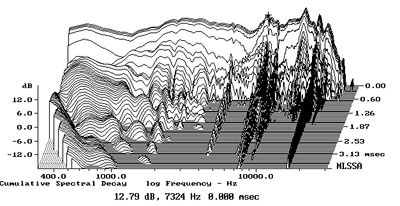
Fig.11 Innersound Kaya, cumulative spectral-decay plot at 50" (0.15ms risetime).

Fig.13 InnerSound Eros Mk.III, cumulative spectral-decay plot at 50" (0.15ms risetime).

Fig.8 MartinLogan Prodigy, cumulative spectral-decay plot at 50" (0.15ms risetime).

Fig.7 Magnepan MG3.6/R, cumulative spectral-decay plot at 50" (0.15ms risetime).

These plots suggest to me that the curved stators of the MartinLogan panels may be more responsible for the hashy CSD plots than is the percent open area. The Aerius (see my previous post) and Prodigy seem to have some features in common, and that differentiate from the flat panel speakers. Of course, it could be some other ML design feature that's the real cause---the curved stator just strikes me as a likely culprit.
Few
The Hash is bad due to the early reflections from using a closed curved stator as opposed to a more open wired stator .
Stator construction and framing will be the determining factor in this, but your explanation 'early reflections' is highly unlikely. Think about the spacing between stators, which is typically a couple of mm, and calculate the wavelength.
These plots clearly show stored energy, which means resonances. This means material choices, dimensions and construction.
Here's a plot of the Quad ESL 57, also a flat plate stator but made from PVC.

@Few
Thanks for posting those measurements, very enlightening.
Thanks Few,
I would put most of the issues on early reflections and curve panels. Notice how clean the quads are in the middle vs the rest . Is there anything on the 63's, would love to see how the 63's compare...
Arend-jan
agree , now look on the panel as a whole and it's accumulation of such. Now perform the same test on a smaller panel open wired and closed perf.
It is not coincidence the quad is pretty good in the middle vs the rest and bad on the top ...
The maggies have the same issues as the perf stator ESL's with it's frame and grille structure make them naked and rejoice ...
Last edited:
Is there anything on the 63's, would love to see how the 63's compare...
I'm having a harder time coming up with good clear measurement results on the ESL63. Here's something extracted from Martin Colloms Nov. 1991 review. Unfortunately, it's just a badly scanned image of the results. An OCR-ed version of the review (with slightly easier to read plots) can be found here. Note that the two CSD plots differ in the dynamic range they span--the upper one is 30 dB and the lower one is 60 dB--and these are to be compared to the 24 dB range displayed in the previous plots. Varying the vertical scale makes a big difference in how clean the plot appears.
An externally hosted image should be here but it was not working when we last tested it.
For what it's worth, I agree with aren-jan that the typical stator spacing (1 - 2 mm) makes it unlikely that reflections between stators cause the hash.
Somewhere I saw a nice explanation of the sources of features in CSD plots. The point, as I recall it, was that ridges along the time axis can have several causes, not just resonances. I wish I could recall where it was; I'd like to reread it. In any case, has anyone ever seen a CSD plot from the back of a curved stator ESL? I'd be interested in what you get if you put the microphone at the focus (center of curvature) of the diaphragm. I'm curious whether making all points on the diaphragm the same distance from the microphone yields a cleaner result. Of course this would only work for all points that are also the same height above the floor, but maybe it would at least hint at whether the panel curvature is responsible for the CSD behavior.
Few
EDIT: Sorry! The previewer didn't show that the scanned image was going to be displayed full size.
Last edited:
Guys ,
I'm not pointing to stator spacing as the culprit , never said that , I'm stating that the accumulated baffle (stator ) is creating so much reflections , this reflective energy is creating the hash . A perf panel will do so more that others unless the panel is pretty small . Nothing to do with stator spacing .
I'm not pointing to stator spacing as the culprit , never said that , I'm stating that the accumulated baffle (stator ) is creating so much reflections , this reflective energy is creating the hash . A perf panel will do so more that others unless the panel is pretty small . Nothing to do with stator spacing .
@Few
Were you thinking about group delay showing in CSD plot perhaps?
@Wayne
If not reflections between the diaphragm/stators, what reflections are you talking about then?
Were you thinking about group delay showing in CSD plot perhaps?
@Wayne
If not reflections between the diaphragm/stators, what reflections are you talking about then?
Hi all. I'm just back from the emergency room after getting my thumb sewed up after it got ripped apart when it got jammed in a beltsander. I'm so careful with my table saw but I let my guard down when using a "harmless" sander. Don't repeat my mistake! The nerve and artery in my thumb were both exposed and nearly severed in the process. Seven stitches later and I'm feeling pretty dumb. 😱 This speaker-building business is dangerous!
I think that the mechanism had something to do with diffracted signals appearing delayed in time as a result of traveling longer distances before reaching the microphone. I'm not confident about that, though. I can't quite come up with ridges parallel to the time axis based on that explanation--unless there are many sources of diffraction.
Man, this one-handed typing is slow...
Few
@Few
Were you thinking about group delay showing in CSD plot perhaps?
I think that the mechanism had something to do with diffracted signals appearing delayed in time as a result of traveling longer distances before reaching the microphone. I'm not confident about that, though. I can't quite come up with ridges parallel to the time axis based on that explanation--unless there are many sources of diffraction.
Man, this one-handed typing is slow...
Few
- Status
- Not open for further replies.
- Home
- Loudspeakers
- Planars & Exotics
- Anyone built roger sanders designs?