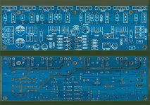
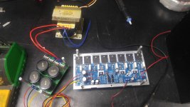
Dual Power Amplifier Board PCB Toshiba 2SC5200 2SA1943 400W Mono High Power AMP
I translated this board to ltspice and I am getting 11% thd on it. Can someone confirm this for me. My asc file is attached. I am new to using ltspice so although I have checked my settings several times, I may be doing something wrong.
I translated this board to ltspice and I am getting 11% thd on it. Can someone confirm this for me. My asc file is attached. I am new to using ltspice so although I have checked my settings several times, I may be doing something wrong.
Attachments
The tails of the long tailed pairs are shorted to ground at AC, one of the zeners (D4) is reversed, the values of R23 and R24 are far too small and preventing Q9 and Q15 from ever conducting - likely to be more issues that fixing those should get the feedback loop working.
I think you invented R23 and R24, just remove them. And some of the 330 ohm resistors should be 220 in the current sources I think. The only 330's are in feedback and input networks.
You may have the topology wrong, I don't see enough gain for the feedback to use. Shouldn't they be current mirror loads?
You may have the topology wrong, I don't see enough gain for the feedback to use. Shouldn't they be current mirror loads?
The board layout looks off to me. That is why I put it in ltSpice. I also could not find any legitimate reviews on these board. Granted I got them for like $7.00. While I was putting them together I kept feeling like something about the layout just didn't seem right. I went over the LTP and Current "Mirror" 5 Times and redrew it every time. I am pretty sure it is correct to whats on the board. The current mirror is not a current mirror it looks like current limiter layout to me.
I just double checked the diodes and I did put one in the wrong direction.
I have seen topology similar to this but the current limiter is usually tied in with the current mirror.
R23 and R24 are correct. They are as laid out on the board. Not sure why they are there. Maybe to add a ton of gain to the output stage.
The only feedback I could find was good but the feedback looks fishy.
I went over this several times and I am pretty sure it is accurate to the board. But what I am getting in the ltSpice tells me that my suspicions may be right.
I am hoping someone has assembled this and can say how good or bad it truly is. I might just fire it up and watch it smoke for fun. Or just be shocked because it works.
Last edited:
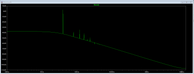
Removing 23 and R24 Brought the THD down to 1.8% I corrected D4 Also.
You were correct about the Q19 and Q7 Resistors. They are supposed to be 220 not 330.
I am not sure what to think about the current mirrors setup though...
You were correct about the Q19 and Q7 Resistors. They are supposed to be 220 not 330.
I am not sure what to think about the current mirrors setup though...
Attachments
Last edited:
It says it all that the 2SD669 that should be on the main heatsink for thermal tracking, is instead on it's own heatsink. Garbage.
It looks like someone's confused constant current sources for current mirrors. It needs the constant current for the tail of each pair, but that's done with a resistor. Modding the board is probably ugly. The layout is bad anyway, the feedback takeoff point is completely wrong for instance.
Agreed. I put the darn thing together and just kept thinking it was wrong. I think I will probably just pull my parts back off and do something different. Next board I buy will not be one that does not come with a schematic and several proven results. I guess this is why these are selling for so cheap. Or not selling. Not many have sold on eBay.
I have used the L20SE for my kids sub and it works good.
I want to build a 2.1 system setup for my computer. I am currently running and older Denon PMA-737 and Yamaha Sub. Sound quality is decent but I want it to be better.
I have used the L20SE for my kids sub and it works good.
I want to build a 2.1 system setup for my computer. I am currently running and older Denon PMA-737 and Yamaha Sub. Sound quality is decent but I want it to be better.
I decided to power this thing up and see what would happen. BOOM! The D669 popped its top.
Question. BD669 VS 2SD669. I cant find a datasheet on the BD669. Are they the same part?
Question. BD669 VS 2SD669. I cant find a datasheet on the BD669. Are they the same part?
I don't think there is such a Prolectron part number as BD669 nor BD649, for that matter.
2S......numbers are Japanese (JIS) original semis.
2N.... numbers are US (JEDEC) original semis.
BC, BD... etc numbers are European (Prolectron) original semis.
These part number series may be all but history now but only by rare coincidence would semis with similar numbers in different series have any similarity to each other.
Edit: These parts are obsolete Hitachi/Renesas transistors which are now Chinese products and come from at least 3 legitimate sources, each having different marks (even a faked Hitachi logo) and part numbers such as "D669" or "HA669". Easy to get confused with cheap kits and the actual semis they supply with them. Some are good parts, others just not up to the task.
Last edited:
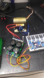
OKY DOKY... I replaced the 2SD669. Check for DC Offset and fired it up again. It actually sounds half way descent but it crapped out after about 1 Hour. It started getting too hot. Way beyond the 3 Second rule... I couldn't hold my finger on the heatsink at all. I think it may require a lot more heatsink and possible some air flow. I think the forward bias is too high too. I still need to verify where it is at. But I need to let it cool off some first.
Pics attached.
Do you guys think this heatsink should be enough?
What would you shoot for on the forward bias? Most of the amps I have worked on it is about 600mv.
Pics attached.
Do you guys think this heatsink should be enough?
What would you shoot for on the forward bias? Most of the amps I have worked on it is about 600mv.
Attachments
Last edited:
+- 43.81 VDC
Voltage drop B to E on output is 0.538 with no signal applied. It has been quite some time since I messed with biasing not sure if I am measuring in the correct spot.
Voltage drop B to E on output is 0.538 with no signal applied. It has been quite some time since I messed with biasing not sure if I am measuring in the correct spot.
With input shorted together, measure voltage drop across an emitter resistor and divide by the resistor value to get the bias current. Example: 19mV DC measured across 0.22 ohm emitter resistor = 0.019V ÷ 0.22 ohm = 0.086A. For class A/B, bias current should be from about 25mA (cool) to 50mA (warm) up to 100mA (hot). Check all separately to see if they are balanced and adjust accordingly so none are over biased. You should be able to adjust the bias current down and get a definite change in heatsink temps.
Not Measured across resistor due to access issues. Measured from emitter to speaker out terminal so values will be a little off. There is not an on board coil. The coil is on my protection circuit.
A1943-1 4.3mv 0.22ohm 19.55ma
A1943-2 4.2mv 0.22ohm 19.09ma
A1943-3 4.3mv 0.22ohm 19.55ma
A1943-4 4.5mv 0.22ohm 20.45ma
C5200-1 4.7mv 0.22ohm 21.36ma
C5200-2 4.6mv 0.22ohm 20.91ma
C5200-3 4.8mv 0.22ohm 21.82ma
C5200-4 4.9mv 0.22ohm 22.27ma
I have been looking at some videos on amp design and I am finding that I really need to move D669 to the same heatsink as the outputs. So that as it heats up it will change the bias characteristics. I am just trying to figure out where to mount it. Not much room.
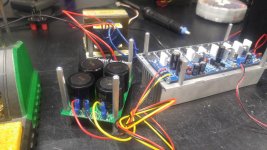
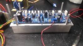
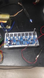
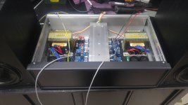
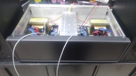
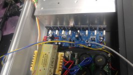
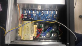
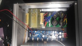
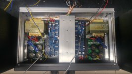
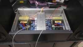
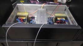
I relocated the Bias Transistor to the heat sink. It has been running for about 1 hour and is not even warm. Still working out details of build but here is what I have so far.
Not too bad for less than 75 Bones. Keeping in mind there was a lot of scrounging parts involved.
Heat Sink is rescued from my Ramsa WP1400 that was totally fried.
Transformers are from a couple of old JVC Subs.
Case was a excess from work that there were scrapping out.
I still need to add Zobel network, Speaker protection and mount everything in the panels.
Attachments
-
 20200130_100728_result.jpg777.6 KB · Views: 112
 -
 20200130_100732_result.jpg729 KB · Views: 90
 -
 20200130_100725_result.jpg351.7 KB · Views: 91
 -
 20200130_100721_result.jpg828.3 KB · Views: 116
 -
 20200130_100717_result.jpg867.6 KB · Views: 115
 -
 20200130_100715_result.jpg779.3 KB · Views: 108
 -
 20200130_100712_HDR.jpg928.5 KB · Views: 127
 -
 20200130_100707.jpg809.2 KB · Views: 121
 -
 20200130_100734_result.jpg810.1 KB · Views: 96
Looks good - I love re-purposing and making an even better amp!
Can you tell me the dimensions of the PCB? Can't find in the ebay ad. Also what voltage did you end up using (just saw it above +/-44.5Vdc) and at what bias current?
Can you tell me the dimensions of the PCB? Can't find in the ebay ad. Also what voltage did you end up using (just saw it above +/-44.5Vdc) and at what bias current?
- Home
- Amplifiers
- Solid State
- Anyone build with this Ebay Board.