Bias Current is 20ma
Specs Copied from eBay Ad. These are the ones I Purchased. They where 4.75 each when I bought them. Most of my parts to assemble them came from recycled amps. I did have to buy the outputs. They were 10.00 for 10 pairs.
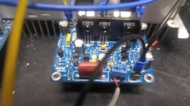
Dual Power Amplifier Board PCB Toshiba 2SC5200 2SA1943 400W Mono High Power AMP 699972494285 | eBay
100% Brand New and High Quality
Mono 400W power amplifier board 1943+5200 power Toshiba tube power amplifier board
Tip: This product is just a PCB blank and does not contain any components. Suppliers do not provide schematics.
The board is mono, does not have rectifier circuit post-amp board, if you need two-channel output, please buy 2pcs bare pcb.
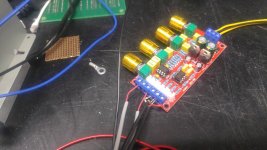
The circuit design uses the A970/C2240 high-withstand-voltage audio pair dual differential circuit, and the A1145/C2705 as the voltage amplification to drive the mid-power pair A1837/C4793, and the output stage uses the A1943/C5200 high-power Toshiba pair for a wide range of power supply. DC positive and negative 20V-50V can be, as long as enough power to easily reach 400W. The sound quality is good and the driving force is very strong. Pushing the 15-inch speaker is no pressure.
Empty board size: 195X60X1.6MM long * wide * high.
Undistorted power: 400W maximum power 600W.
Power supply: DC ± 20-50V (recommended voltage: -30V 0 +30V).
High voltage (up to ± 90V) is required. Replace the electrolytic capacitor on the board (for high voltage capacitors).
There is a placemark 2K and 330 on the board, which means that you can solder 2K adjustable resistors here, and you can also solder the 330ohm resistor.
104 is the capacitance, 104*6 is where there are 6 components welding 104 = 0.1uF capacitance, 221 is 220pF capacitance, 220 and 330 is the resistance unit is EU 104 * 6 means that these six places are welded 0.1uF capacitor . OUT is the output. 104 represents a 0.1uF capacitor.
Capacitance voltage value is 50V.
Specs Copied from eBay Ad. These are the ones I Purchased. They where 4.75 each when I bought them. Most of my parts to assemble them came from recycled amps. I did have to buy the outputs. They were 10.00 for 10 pairs.
Dual Power Amplifier Board PCB Toshiba 2SC5200 2SA1943 400W Mono High Power AMP 699972494285 | eBay
100% Brand New and High Quality
Mono 400W power amplifier board 1943+5200 power Toshiba tube power amplifier board
Tip: This product is just a PCB blank and does not contain any components. Suppliers do not provide schematics.
The board is mono, does not have rectifier circuit post-amp board, if you need two-channel output, please buy 2pcs bare pcb.
The circuit design uses the A970/C2240 high-withstand-voltage audio pair dual differential circuit, and the A1145/C2705 as the voltage amplification to drive the mid-power pair A1837/C4793, and the output stage uses the A1943/C5200 high-power Toshiba pair for a wide range of power supply. DC positive and negative 20V-50V can be, as long as enough power to easily reach 400W. The sound quality is good and the driving force is very strong. Pushing the 15-inch speaker is no pressure.
Empty board size: 195X60X1.6MM long * wide * high.
Undistorted power: 400W maximum power 600W.
Power supply: DC ± 20-50V (recommended voltage: -30V 0 +30V).
High voltage (up to ± 90V) is required. Replace the electrolytic capacitor on the board (for high voltage capacitors).
There is a placemark 2K and 330 on the board, which means that you can solder 2K adjustable resistors here, and you can also solder the 330ohm resistor.
104 is the capacitance, 104*6 is where there are 6 components welding 104 = 0.1uF capacitance, 221 is 220pF capacitance, 220 and 330 is the resistance unit is EU 104 * 6 means that these six places are welded 0.1uF capacitor . OUT is the output. 104 represents a 0.1uF capacitor.
Capacitance voltage value is 50V.
thanks - exactly what I needed to know. I guess your thread has driven prices up, they are $6.50/ea now?!?!
thanks - exactly what I needed to know. I guess your thread has driven prices up, they are $6.50/ea now?!?!
Off topic... Sorry cant resist.
Stang Lover???
Me Too...
Here is mine
Attachments
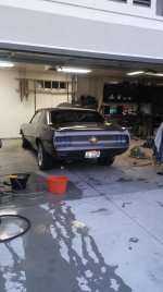
Wow - that's a cool interpretation of a classic! Did you buy it modified, or are you also a metal worker, modifier?
All me. It was my goal to do it all myself. I learned a lot along the way. It took way too much time.
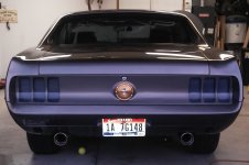
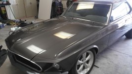
Shaved Drip Rails, Shaved Door handles, Cut and tucked bumper, Flattened firewall, Custom Tail Lights, and Custom Side Marker lights. The rest of the body is original 1969 Mustang.
Shaved Drip Rails, Shaved Door handles, Cut and tucked bumper, Flattened firewall, Custom Tail Lights, and Custom Side Marker lights. The rest of the body is original 1969 Mustang.
you did a great job and nice color choice, highlights it's totally custom.
Thanks.
Bias Current is 20ma
Did you mean 20mV measured across one of the 0.22r resistors? 20mA would be 4-5mV across that resistor, which seems low.
Also wondering how hot the heatsinks get after 30-60 minutes of music? Pretty beefy heatsinks, but curious how hot 4-pairs of BJTs get.
Trying to plan out a 5-channel HT build and I'd love to use 4-pair BJTs at +/-65Vdc, but not sure my heatsinks can handle the heat, as cramped as the chassis will be with everything installed.
edit - any turn-on thumps, or weird noises? Hum, hiss, etc. when it's on but not playing anything?
Measured the across the 0R22 resistors. It was 20ma not 20mv. I did not use an adjustable bias potentiometer. I might try replacing the 330 ohm and play with that. I am keeping the bias low until I prove the circuit is stable.
Ran it for 4 hours today with the volume up enough that you could not carry on a conversation with it playing. It barely got warm. You could feel a little heat from it but not even close to be of any concern. There is a slightly notable noise floor that you can hear if you get your ear right up to the tweeter. No turn on thump. When you power it down with a signal applied it will run for 30 to 45 seconds before the filter caps drain enough to shut down.
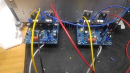
I had a heat issue to start with. I relocated the D669 Bias transistor to the heat sink and it cured the heat issue.
Noise floor could be from the 12 foot cable I have running from my laptop to it. I think it is in the amp though. I actually think is has to do partly with the cap boards I used. They are just the bridge and 4 filter caps. There are no bleeder resistors or .1uf cap on them. Not the best filter board. However it is 40,000uf of capacitance per channel.
Next step in my tinkering with it is to hook it up to a 4 ohm 200w load resistor and see if I can get it to heat up running hard.
Then add some bleeder resistors and small caps. See what that does to the noise floor and shutdown time.
Ran it for 4 hours today with the volume up enough that you could not carry on a conversation with it playing. It barely got warm. You could feel a little heat from it but not even close to be of any concern. There is a slightly notable noise floor that you can hear if you get your ear right up to the tweeter. No turn on thump. When you power it down with a signal applied it will run for 30 to 45 seconds before the filter caps drain enough to shut down.
I had a heat issue to start with. I relocated the D669 Bias transistor to the heat sink and it cured the heat issue.
Noise floor could be from the 12 foot cable I have running from my laptop to it. I think it is in the amp though. I actually think is has to do partly with the cap boards I used. They are just the bridge and 4 filter caps. There are no bleeder resistors or .1uf cap on them. Not the best filter board. However it is 40,000uf of capacitance per channel.
Next step in my tinkering with it is to hook it up to a 4 ohm 200w load resistor and see if I can get it to heat up running hard.
Then add some bleeder resistors and small caps. See what that does to the noise floor and shutdown time.
Thermal Study results.
R = Right Amp
L = Left Amp
V = Volume
Speakers are Yamaha NS-AP2600S
All Temperatures in Fahrenheit
Room Temperature is 65 F
Lid Removed. No Forced air.
Measure between N and P Sets right under bias Transistor.
Comparison of all output is less that 2 degree variation.
Measurement on actual transistor averages 4 degrees warmer.
Measurement made with IR Thermometer.
9:12A Starting Temperature 60
9:27A R87.4 L78.4 V12
9:41A R92.1 L81.3 V12
9:46A R94.3 L80.8 V12
9:47A Increase V to 20
9:54A R98.2 L83.8 V20
10:06A R94.3 L89.1 V20
10:07A Decrease Volume to 10
10:13A R92.5 L87.3 V10
10:31A R90.7 L86.2 V10
11:04A R91.8 L86.2 V10
11:05A Increase V to 50.
11:10A R92.8 L91.0 V50
11:16A Increase Volume to 80
11:18A R96.1 L92.5 V80
11:19A Decrease V to 30
11:20A R98.1 L92.3 Heatsink Top is a 102.6
11:24A R Transformer 97.9 L Transformer 97.6 R Caps 72.1 L Caps 69.8
11:26A Increase V to 50
11:32A R100.6 L88.7 V50
11:34A PC Hookup up Music Paused.
11:40A R97.2 L91.4 V0
11:48A R93.6 L87.1 V0
11:59A R95.6 L87.9 V0
12:06P R93.2 L88.2 V0
12:14P Input Cable Removed. R96.5 L86.7
Power Off
Thanks for temps, very thorough.
What about hiss/hum noise? Did you get that resolved or lessened?
Most important - how does it sound?
What about hiss/hum noise? Did you get that resolved or lessened?
Most important - how does it sound?
It sounds very good. I need to hook it up to a sub-woofer and see how it does with low bass.
Noise was a really dumb. It was my Cable. I moved it and the hiss went away. New cable solved it.
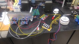
I am currently working on the other 4 Channels. MX50SE. Still in the messy stage.
Noise was a really dumb. It was my Cable. I moved it and the hiss went away. New cable solved it.
I am currently working on the other 4 Channels. MX50SE. Still in the messy stage.
Attachments
-
 20200209_143206_resize.jpg146.5 KB · Views: 109
 -
 20200209_143205_resize.jpg125.9 KB · Views: 100
 -
 20200209_143201_resize.jpg104.9 KB · Views: 101
 -
 20200209_143154_resize.jpg80.3 KB · Views: 91
 -
 20200209_143146_resize.jpg149.1 KB · Views: 88
 -
 20200209_143144_resize.jpg156.9 KB · Views: 196
 -
 20200209_143140_resize.jpg140 KB · Views: 183
 -
 20200209_143137_resize.jpg154.1 KB · Views: 179
 -
 20200209_143134_resize.jpg160.8 KB · Views: 186
 -
 20200209_143131_resize.jpg157 KB · Views: 205
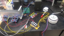
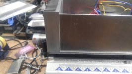
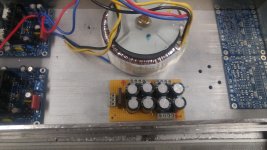
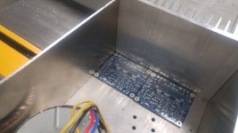
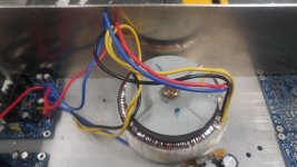
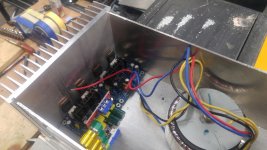
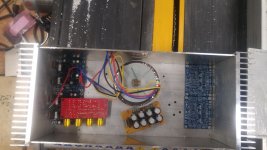
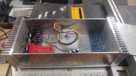
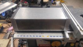
Update on the MX50SE Case. Work in progress.
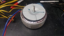
Hoping to find a bigger transformer. This one is on the small side. It is 250VA 48V (24 0 24) After rectifier.
Hoping to find a bigger transformer. This one is on the small side. It is 250VA 48V (24 0 24) After rectifier.
Attachments
-
 20200212_224819_resize.jpg113.5 KB · Views: 58
 -
 20200212_224808_resize.jpg139.7 KB · Views: 80
 -
 20200212_224802_resize.jpg114.3 KB · Views: 70
 -
 20200212_224800_resize.jpg110.5 KB · Views: 80
 -
 20200212_224757_resize.jpg136.8 KB · Views: 83
 -
 20200212_224742_resize.jpg152.6 KB · Views: 83
 -
 20200212_224733_resize.jpg134.3 KB · Views: 75
 -
 20200212_224729_resize.jpg118.5 KB · Views: 92
 -
 20200212_224717_resize.jpg115.1 KB · Views: 81
 -
 20200212_224823_resize.jpg89.7 KB · Views: 67
Last edited:
MX50SE is a pretty nice kit. Sounds and measures better with the Sanken transistors, but KEC is ok to. Cranking up bias makes it even better when listening at normal levels. I would recommend a bigger input cap if you plan to use them for bass too.
Caps in PS look a bit small?
Caps in PS look a bit small?
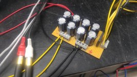
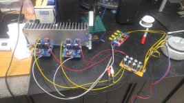
The cap board was tossed together with what I had laying around. It is definitely not the final one. It is the bare minimum to test the boards with.
Caps are 2200uf at 35V (8800uf per supply) I will probably change the caps to 4700 @ 50V and upgrade the transformer to a 600va at 30-0-30. Or add another toriod just like this one that I have in a box somewhere.
I want to see how it would do with Toshiba A1943 C5200 but that's a project for another day. Plus I need to see if anyone has any luck with them.
Which Sankens are you referring to? Do you mean the 2SA1494 2SC3858 Pair? I think I have a couple of those laying around somewhere. I definitely have several pairs of the Toshiba's
The bigger amp earlier in this thread is for my subs.
Ok.
I mean 2sc3264/2sa1295, they have been sold as a kit with mx50se too.
I'm testing MJL 1302A/3281A, and they seem to measure good on distortion too, and seems stable. Iq for lowest dist, more than 0,2A, you can try up to abt 0,6A if you have enough heat sink capacity.
I mean 2sc3264/2sa1295, they have been sold as a kit with mx50se too.
I'm testing MJL 1302A/3281A, and they seem to measure good on distortion too, and seems stable. Iq for lowest dist, more than 0,2A, you can try up to abt 0,6A if you have enough heat sink capacity.
- Home
- Amplifiers
- Solid State
- Anyone build with this Ebay Board.