I can tell you that cathodyne phase splitters produce virtually no "tone", because they operate with lots of negative feedback. You have to push one very hard to hear any audible distortion from it - and if you do, it is ugly distortion. Usually the output valves have gone deep into clipping before the cathodyne gets there, so you don't hear anything from the cathodyne stage.But I am still on the fence as to whether that cool, lush tube distortion comes from the Input tubes, Phase Inverter, or output tubes...
Because of this, a cathodyne is ripe for replacing with a MOSFET. There is no change in tone, and this frees up one triode to be better used somewhere else in the circuit, where you can actually benefit from it.
IMO, every other guitar amp stage (input, long-tailed-pair phase splitters, output tubes) produces audible amounts of distortion. I've verified this for myself over the years. Input stages typically produce very subtle amounts of distortion, but it is quite audible if you have a good pair of ears.
-Gnobuddy
12AX7 into a 6V6? What are tubes?
EDIT - OK, cannot be 6V6/6L6 family....
EDIT EDIT - its an EL84...OK, now I like it....
EDIT - OK, cannot be 6V6/6L6 family....
EDIT EDIT - its an EL84...OK, now I like it....
Last edited:
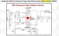
I did draw it up for EL84 but it does not matter, can be 6V6, 6L6, whatever tube you want. I deleted the tube type, thought the numbers were a part of the pentode symbol, seems I was wrong and I can delete them. Pretend they are not there. The phase inverter does not care. The peak signal the preceding stage will put out what it can given the voltage it is running at. Running a 6L6, use a higher voltage. Just increasing the supply voltage with the same circuit will give the 6L6 more to work with and will give the preceding stages more voltage resulting in a greater drive signal. The same circuit can be used with 6AK6's. The cathode resistor on the output stage would have to be appropriate though. I had the same circuit drive a pair of 6AQ5's (OK, 12AQ5's). The voltage the PI is given and the preceding stages also if you wanted them to clip at a particular point but for a clean amp that is less of an issue. As it stands, the output will distort first, which every non-master volume amp should do. Actually master volume amps also, some people do not get that though.12AX7 into a 6V6? What are tubes?
EDIT - OK, cannot be 6V6/6L6 family....
EDIT EDIT - its an EL84...OK, now I like it....
Using a LND150,

Not a traditional layout but I wanted it to fit on the board I had. Look, I did have the schematic drawn up already (could not find it and quickly modified another one ).

Last edited:
Hey Print - why not add a master volume with a single 1M analog pot? Simple...then you can run the preamp tubes harder than the output tubes.
BTW - I have played with those LND150... they are essentially Solid State 12AX7. I fit them into noval bases and fill with wax...
BTW - I have played with those LND150... they are essentially Solid State 12AX7. I fit them into noval bases and fill with wax...
Attachments
The OP wants a clean amp, a master volume is not in his interest. And with a cathodyne PI, or the Mosfet version could just as well have a voltage divider Pot after the second stage. All kinds of fun to be had.
The value of the common cathode resistor (270 Ohm) is is more than double the value given in the datasheets for the EL84 (130 Ohm).A clean amp you say?

Are you sure about the value of the common cathode resistor (220 Ohm)? When looking at the curves or the 12BK5, and assuming a B+ of around 250 V, for normal push-pull operation the cathode voltage of the 12BK5's should be somewhere between 5 and 6 V and the total current (for the two 12BK5's) would be somewhere around 65 mA. But with a total current of 65 mA and a common cathode resistor of 220 Ohm, the cathode voltage would be 14.3 V instead of somewhere between 5 and 6 V.I did draw it up for EL84 but it does not matter, can be 6V6, 6L6, whatever tube you want. I deleted the tube type, thought the numbers were a part of the pentode symbol, seems I was wrong and I can delete them. Pretend they are not there. The phase inverter does not care. The peak signal the preceding stage will put out what it can given the voltage it is running at. Running a 6L6, use a higher voltage. Just increasing the supply voltage with the same circuit will give the 6L6 more to work with and will give the preceding stages more voltage resulting in a greater drive signal. The same circuit can be used with 6AK6's. The cathode resistor on the output stage would have to be appropriate though. I had the same circuit drive a pair of 6AQ5's (OK, 12AQ5's). The voltage the PI is given and the preceding stages also if you wanted them to clip at a particular point but for a clean amp that is less of an issue. As it stands, the output will distort first, which every non-master volume amp should do. Actually master volume amps also, some people do not get that though.
Using a LND150,
Not a traditional layout but I wanted it to fit on the board I had. Look, I did have the schematic drawn up already (could not find it and quickly modified another one ).
I changed it as the OP was talking about 6V6's.The value of the common cathode resistor (270 Ohm) is is more than double the value given in the datasheets for the EL84 (130 Ohm).
On the *BK5,
https://www.vtadiy.com/loadline-calculators/loadline-calculator/
B+ 300V, 30mA, 10k, screen 280V. Grid bias 7V. 10W. 220 x 0.030 = 6.6V
Close enough for a first try. Usually I would use a step or two higher value resistor and put a parallel resistor to trim it. I just put a target value in.
In post #24 you wrote that you drew up the schematic in post #22 for EL84's (b.t.w.: the common cathode resistor is drawn shorted).
About the schematic with the 12BK5's in post #24: At Vg2 = 280 V and Vg1 = - 7 V the plate current of a single 12BK5 would be something like 28 mA. So for two 12BK5's the combined plate current would be something like 56 mA. The combined screen grid current should be added to this 56 mA so the total current through the common cathode resistor would be something like 60 mA, so about two times your number.
I get the impression that you calculate the value of the cathode resistor for one tube only, giving you the value that each cathode resistor should have if you would use two seperate cathode resistors. But this value should be devided by 2 when using a common cathode resistor.
Last edited:
Need to fix that. Sloppy cut and paste from another schematic.In post #24 you wrote that you drew up the schematic in post #22 for EL84's (b.t.w.: the common cathode resistor is drawn shorted).
About the schematic with the 12BK5's in post #24: At Vg2 = 280 V and Vg1 = - 7 V the plate current of a single 12BK5 would be something like 28 mA. So for two 12BK5's the combined plate current would be something like 56 mA. The combined screen grid current should be added to this 56 mA so the total current through the common cathode resistor would be something like 60 mA, so about two times your number.
I get the impression that you calculate the value of the cathode resistor for one tube only, giving you the value that each cathode resistor should have if you would use two seperate cathode resistors. But this value should be devided by 2 when using a common cathode resistor.
Didn't calculate it. Assumed the calculator would give the current through two tubes since it was set to P-P. As you say, should be half. Really dumb mistake considering the current is right there on the graph. Brain fart.
Last edited:
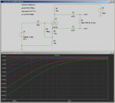
That particular master volume (from Ken Fischer) is a very poor design - it is actually an (accidental) bass cut filter, rather than a master volume. As you turn down the "master volume", bass is dramatically cut, while treble level is almost unaffected....why not add a master volume with a single 1M analog pot?
This is because the two coupling caps from the cathodyne act as high-pass filters with the resistance of the "master volume" pot. As the resistance is reduced, the cutoff frequency is raised, and bass is cut more and more severely.
The attached LTSpice simulation shows what this particular "master volume" actually does. R5 is the 1M pot. As the graphs show, turning the pot has almost no effect at all on frequencies above 2 kHz - all it does is remove all the deep bass.
This is exactly the opposite of what we want, by the way; as SPL is turned down, our ears don't hear bass as well (Fletcher-Munson effect). A good master volume would, if anything, turn up the bass as the overall level is turned down. This particular master volume does the opposite.
The simulation shows 0.047 uF (47 nF) coupling caps from the cathodyne, which is the value I found elsewhere. The circuit John65b posted uses 0.1uF (100 nF) caps. This will have the effect of shifting the curves in the LTSpice simulation to the left by one octave - but it won't fix the major fault in this "design", i.e., it is actually a variable bass cut, and not a master volume at all.
In the circuit John65b posted, this problem can be fixed, very simply, by raising the value of the grid stoppers for the output valves from 1.5k to about 100k each. That will allow the master volume to actually work as a master volume, rather than as a bass cut control.
As a beneficial side effect, 100k grid stoppers reduce blocking distortion and improve overdrive tone.
Worth a mention - input capacitance of EL84s in this type of circuit is in the vicinity of 35 pF. This means 100k grid stoppers won't have any audible effect on guitar treble frequencies, contrary to popular concerns.
-Gnobuddy
Attachments
Gno - Ha! Thanks for the update. I snipped that from Rob Rabinettes site....I have been looking to put that MV in one of my amps for a while....I may just do it soon....with your correction
Most often the Lar-Mar master volume adaptation of the Type 2 MV is used instead. You can find it easily online.
Gnobuddy, what about the existing 220K resistors before the grid blockers - aren't they going to dominate the high pass behaviour? (yes, I'm too lazy to fire up pspice 🙂 )
They do indeed - until you turn down the master volume pot!...what about the existing 220K resistors before the grid blockers - aren't they going to dominate the high pass behaviour?
One way to visualize this: there are equal-amplitude antiphase signals at the two ends of the 1M master volume pot. From symmetry, the centre of that resistance must then be at zero volts.
When the pot is at its full 1M resistance, each half is 500k, in parallel with the 220k grid bias resistor. That lowers the effective value of the grid bias resistor to about 153 k.
While a significant reduction, this isn't enough to have any bad effects. The corner frequency of the high-pass filter is still low enough not to be a problem - it's 22 Hz with 47nF coupling caps, i.e. two octaves lower than the lowest frequency (82.4 Hz) you'll get from a guitar in standard tuning.
Now imagine that 1M pot turned down to one-tenth of its end-to-end resistance, i.e. half-rotation on a log pot. This time you have a 50k resistor in parallel with each of the 220k grid bias resistors. Each grid bias resistor is now effectively only 40.7 k, and the high-pass filter kicks in below 83 Hz. This is still not high enough to be a big problem, but the situation starting to become marginal. Master volumes are not supposed to muck with the frequency response, but this one has already introduced 3 dB of bass cut at the low frequency end of a guitar's range.
Now imagine the 1M pot turned down to half of half - i.e. one-quarter of its rotation, at which point its resistance is one-tenth of one-tenth of 1M. That's only 10k. Half of that is only 5k, and this is in parallel with each of the 220k grid bias resistors.
If we pretend the cathodyne has zero output impedance, the high-pass filter corner frequency is now 696 Hz. This is close to the musical note F5 ( https://pages.mtu.edu/~suits/notefreqs.html ), which is the note on the 13th fret of the thinnest guitar string. Every frequency below this has been attenuated!
At this point, it's not just that the deep bass has been removed. Almost the entire guitar signal has been gutted, except for frequencies above 1 kHz or so. All that's left is a very thin sound, like someone listening to a guitar on their mobile phone's built-in speaker.
Not only is this MV an accidental bass-cut filter, it also fails to actually silence the guitar signal - those annoying screechy high frequencies above 1 kHz will still get through at full volume, even with the MV turned most of the way down to zero!
In practice the cathodyne stage does have some output impedance, particularly on the anode side, and since this is in series with the coupling-capacitor reactance, it will eventually staunch the bleeding as the MV pot is turned lower and lower. In other words, the frequency-independent cathodyne output impedance will eventually swamp out the reactance of the cathodyne coupling caps, limiting how high the corner frequency of the accidental high-pass filter can go. It will never get as high as, say, 7000 Hz.
But as the LTSpice simulation shows, the damage is done long before this this small second-order effect kicks in. As-designed, the guitar signal is gutted when you turn the MV down below one-quarter of its rotation (this is for the usual log or "audio" pot, with the usual 10% taper).
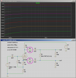
The way the cathodyne output impedance limits the damage suggests a simple and easy fix. Artificially raising the output impedance of the cathodyne with a series resistor in each output signal will do the trick (see second attached image).
Instead of a variable high-pass filter, we now have more or less flat frequency response across, with the overall level dropping as the MV is turned down. In other words, we now actually have a master volume, rather than a variable bass cut filter!
The simplest way to raise the cathodyne output impedance is simply to wire the MV pot directly across the output (control) grids, as in the image John65b posted, and then raise the value of the 1.5k output-valve grid stoppers to somewhere in the 47k - 100k range.
The last time I brought up the fact that Ken Fischer's MV doesn't work properly on a public forum, someone suggested that the problem with Fischer's MV design wouldn't exist once the amplifier's output stage was included in the simulation. That isn't the case - the third picture shows the LTSpice simulation including output valves.
-Gnobuddy
Attachments


Yeah but, if the amp has NFB the NFB will counteract the volume pot until the amount of gain the loop has is used up. Mind you a dual pot will also be not with the frequency effects.
Agree about the effect of overal negative feedback, but I didn't understand the quoted part of your post - could you please clarify?Mind you a dual pot will also be not with the frequency effects.
-Gnobuddy
What the heck? Missing a piece in the middle. Stupid computer swaps memory to the HD and at times freezes up. Guess I did not read it after I typed (couple finger typer so I look down at the keyboard). I can not remember the missing phrase but it was to say the dual pot will also use up the gain when turned dow, possibly I was saying without the frequency effect.Agree about the effect of overal negative feedback, but I didn't understand the quoted part of your post - could you please clarify?
-Gnobuddy
Good to see you on again, hope you did not get washed away.
Thanks! We got close enough to have some water intrusion into the basement storage lockers in our apartment building, but thankfully, nothing worse than that.Good to see you on again, hope you did not get washed away.
Every day feels like playing Russian Roulette with mother nature now. Will it be wildfires today? Drought? A killer heat-wave? Torrential rainfall and flooding? Unmanageable amounts of snow? Another deadly COVID-19 variant?
-Gnobuddy
- Home
- Live Sound
- Instruments and Amps
- Any Suggestions For a Clean Amp Design?