Looks like the MPSA42 is still available, wonder how much longer for....
MPSA92 doesn't look as it would be quite so easy to get hold of.
Using SMD might allow the saved space to be used for maybe onboard fuses and speaker protection, while still keeping the compact overall size of the PCB.
MPSA92 doesn't look as it would be quite so easy to get hold of.
Using SMD might allow the saved space to be used for maybe onboard fuses and speaker protection, while still keeping the compact overall size of the PCB.
Just checked on line and the mpsa92's £2.49 for 25 of them.
Sounds like your be spice filing a circuit up soon
Sounds like your be spice filing a circuit up soon
And for the vas current mirror mje340 and mje350...
The old circuit just had a 1k trim pot to set the q current from 50ma to 110ma.. yes we know fet's ptc..but this little circuit has so may ways to mod it to suit the users needs.
Even catch diodes from the output to each supply rails.
The old circuit just had a 1k trim pot to set the q current from 50ma to 110ma.. yes we know fet's ptc..but this little circuit has so may ways to mod it to suit the users needs.
Even catch diodes from the output to each supply rails.
Just checked on line and the mpsa92's £2.49 for 25 of them.
Sounds like your be spice filing a circuit up soon
Haha, I wish ....
Design I would leave up to someone far more knowledgeable than myself, you would think that 40+ years in the electronics industry I would have a solid know how and understanding of how to build and design from the ground up, but I don't.
Yet, I can take a failed aircraft computer, Amp, Whatever, and providing I have a Circuit diagram, Scope, DMM.. etc, and fix it.
It's like formula's, Until I see a formula with an example, except for the really easy ones, I might just as well be staring at a blank page 😕
We are all knowledgeable in our own area's..from valve amps to solid state transistor amplifiers.
There are plenty of basic amp circuits out there to try and at the end of day we choose one that suits our needs.
There are plenty of basic amp circuits out there to try and at the end of day we choose one that suits our needs.
I would like to see the Maplin Mosfet Amp, lets say given a make over, or bought up to date, while retaining it's simple design and compact size, with all of the ideas and little changes mentioned throughout this thread incorporated into a new PCB Layout.
I suppose it's a case of if enough people think it is a worthy contender of upgrading or updating.
I suppose it's a case of if enough people think it is a worthy contender of upgrading or updating.
I wonder how many people here have Maplin amps that they would like to upgrade...perhaps keeping the original FETs and transferring them to a new board with a better circuit?
That would be something I'd like to do.I wonder how many people here have Maplin amps that they would like to upgrade...perhaps keeping the original FETs and transferring them to a new board with a better circuit?
Some thoughts...
- Splitting supply into frontend and FET's, since frontend / gate drive has to swing remarkably above output (source) voltage
- more current to drive the FET's
- forward gain path as linear as possible, allowing even no or low feedback experiments (eg by loading the VAS or higher input device degeneration
- FET's as input devices (LSK / SK170, J113, ...) or complementary input
Just thinking loud...
After some more thinking, no Feedback would not be the way to go as these FET's have quite low transconductance, and there is only one pair.
Maybe experimenting with negative AND positive feedback (à la Pass) could be interesting.
Maybe experimenting with negative AND positive feedback (à la Pass) could be interesting.
Yep, I see the original design as being suitable only for 8 ohm loads.
From a point of view of keeping the original design, and considering sensible enhancements, I can see a wish list forming from this thread:
Support for 2 parallel pairs of output devices
Current limiting / Vgs zener clamps
DC offset protection / output clamp
Direct-to-heatsink mounting
First stage current source
Improve layout WRT grounding and decoupling
Gate resistors closer to devices
.. and then we could get into a complete redesign, of course.
Hello ...
Ok cant hold back any longer as I have been working on a new design based on the upgraded Maplin unit
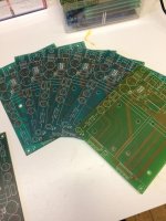
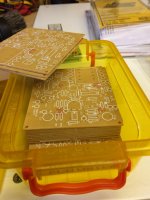
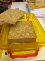
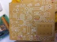
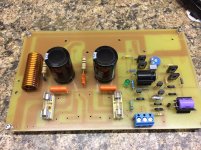
but I have some retro boards ... the original maplin amplifier power supply boards, when was the last time you saw some of these ??
Ok cant hold back any longer as I have been working on a new design based on the upgraded Maplin unit
but I have some retro boards ... the original maplin amplifier power supply boards, when was the last time you saw some of these ??
Attachments
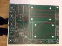
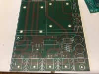
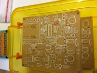
this is my new uprated Maplin module ... still work in progress .. but is very similar to the maplin schematic but with a LED bias for the long tailed pair input .. and a very heavy duty PCB with thick high current tracks .. but all based on the same design
The experts amongst you will recognize the PCB ??
The experts amongst you will recognize the PCB ??
Attachments
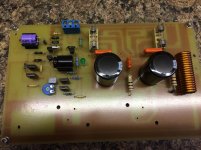
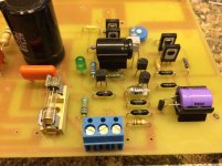
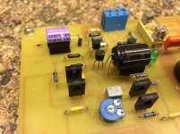
Just looking at your circuit boards there...where's the input coupling cap so dc does'nt feed into the tail pair.
Plus some catch diodes can be added from the output to each supply rails
Plus some catch diodes can be added from the output to each supply rails
- Home
- Amplifiers
- Solid State
- Any Maplin MosFet Amp Guru's on here?