After trying mica and aluminum oxide ceramic insulators which gave me temperature 8-10C higher than directly mounted transistors I tried an intermediate small heatsink between a transistor and large heatsink.
This intermediate heatsink has much larger area than a transistor and even with a crappy thermal interface can conduct enough amount of heat from transistors to big heatsink.
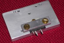
So, a transistor is directly attached to a small heatsink (60x60x8mm aluminum plate). To insulate small heatsink from a big one I used a frame cut from transparent film for laser printers. This film easily survives laser printer heater (180C) w/o be scratched/melted. The thickness of film is 4-5 mils (~0.1mm).
The 0.1mm gap between small and big heatsinks is filled with high quality non-conductive thermal compound. I used Arctic Cooling MX-2 which has good thermal conductivity (5-6 W/mK, mica has only 0.3-0.4 W/mK) and high
dielectric strength (10-15 kV/mm). The small heatsink has a mounting hole where transistor's hole is. Additionally I used a washer made from the same film which placed between small and big heatsink in place where the mounting bolt goes through. To avoid the bolt touching small heatsink the hole in it is twice bigger than mounting bolt and insulating hub is used (I made one using same printer film).
So, I've got transistor insulated from the heatsink with maximum possible thermal conductivity.
This intermediate heatsink has much larger area than a transistor and even with a crappy thermal interface can conduct enough amount of heat from transistors to big heatsink.
So, a transistor is directly attached to a small heatsink (60x60x8mm aluminum plate). To insulate small heatsink from a big one I used a frame cut from transparent film for laser printers. This film easily survives laser printer heater (180C) w/o be scratched/melted. The thickness of film is 4-5 mils (~0.1mm).
The 0.1mm gap between small and big heatsinks is filled with high quality non-conductive thermal compound. I used Arctic Cooling MX-2 which has good thermal conductivity (5-6 W/mK, mica has only 0.3-0.4 W/mK) and high
dielectric strength (10-15 kV/mm). The small heatsink has a mounting hole where transistor's hole is. Additionally I used a washer made from the same film which placed between small and big heatsink in place where the mounting bolt goes through. To avoid the bolt touching small heatsink the hole in it is twice bigger than mounting bolt and insulating hub is used (I made one using same printer film).
So, I've got transistor insulated from the heatsink with maximum possible thermal conductivity.
very elegant solution. A bit like a heat spreader. The thermal resistance is in the insulation so with a greater area to insulate you can get the resistance down.
great tip! Thanks for the write-up!
great tip! Thanks for the write-up!
After trying mica and aluminum oxide ceramic insulators which gave me temperature 8-10C higher than directly mounted transistors I tried an intermediate small heatsink between a transistor and large heatsink....
What's the temp. difference now (using the same comparison method) ?
I assume all your collectors are at the same potential ;p
But seriously, like juma asked, did it result in lower temps ?
Of course you could take this approach all the way, and insulate the whole heatsink ...
But seriously, like juma asked, did it result in lower temps ?
Of course you could take this approach all the way, and insulate the whole heatsink ...
The idea is nice and and simple - to thermally extend the transistor's case, but the contact area between new/bigger transistor's case and the main heatsink also becomes bigger.
That's why I wanted to know - is the temp. of the original transistor's case lower now than it was before (all other things being equal)?
That's why I wanted to know - is the temp. of the original transistor's case lower now than it was before (all other things being equal)?
The idea is nice and and simple - to thermally extend the transistor's case, but the contact area between new/bigger transistor's case and the main heatsink also becomes bigger.
That's why I wanted to know - is the temp. of the original transistor's case lower now than it was before (all other things being equal)?
Depends on the thermal resistance of that laser printer sheet, which is probably not optimized for low Rth. The idea is very good, and will work best if you use as insulation the same material as is used for the 'normal' insulation parts. The thermal insulation rubber (don't know the exact name) can be bought as sheets, so you can cut it to size. That would work best here.
jd
Depends on the thermal resistance of that laser printer sheet....
jd
Off course, and if frags can confirm measured improvement with that laser printer foil, we can have even better results with Rth-specialized materials (kapton and mica can be found in ribbons/sheets and cut to custom size)
This sounds good, but I imagine plastic like this might have a significant dielectric constant. Do you think this could be a problem with the amount of area, becoming a small capacitor relative to the device?
I wonder if we could try paper soaked with oil as an insulator here. Boiled linseed oil comes to mind here, which has a puncture voltage of around 300V per mil. If we soak printer paper in it, we have about 4 mils of thickness which gives 1.2kV tolerance. Perhaps instead of using the paper immediately after soaking we can wait until it dries and then see how well it works? Doable?
I don't know if there would be a temperature problem. But if we use the paper when it's still wet, the oil on the outside of the device will dry, possibly sealing in the oil between the device and heatsink, preventing it from drying.
Good idea, frags. I will put this in my bookmarks.
- keantoken
Polyester (the material used for those overheads) has a lower dielectric constant than the metal oxides. And much lower thermal conductivity, alas. As thick as it is compared to, say, a mica insulator, the capacitance will be lower. Temperature measurements of the small and large heatsink will give you a more quantitative idea of the thermal resistances.
About temperatures:
Initial conditions - 30W transistor dissipation, big heatsink is blown with 12cm fan to keep it as cool as possible.
When the transistor was mounted directly to big heatsink it showed ~43C оn its case (I'm using IR thermometer). With mica insulator the temperature was ~51-52C. With intermediate small heatsink it was ~43-44C.
In the past I red an article of one guy who measured temperature difference between transistor (TO-220 case 20W) bottom and heatsink with different insulators. Here it is:
1. No insulation - 1C
2. BeO ceramic (0.85mm) - 3C
3. AlO3 ceramic (1.0mm) - 8C
4. Mica (0.2mm) - 23C (this mica is too thick, the good one with 0.05-0.07mm will give same as AlO3 ceramic)
5. Silicon rubber - 30C
About insulator I used. First of all I did not use solid sheet of insulator but a frame with 5mm side width, so the frame would not give big effect for capacitance and thermla conductivity. The thermal paste MX-2 has dielectric constant 9 (it's based on AlO3), mica has 7.
PS. I can measure capacitance between small and big heatsinks.
PS. I can measure capacitance between small and big heatsinks.
And of course you can use mica, Polyester, paper or fiberglass. I used that what I found handy in my home at that moment.
Glue
What I have done on a gainclone is bolting the chip to a block of alu 60 x 50 x 5 mm both tab and clamp, unisolated with silicone grease. Then the block was glued with thermal conducting, electrically isolating glue. I used locktite 315 from Farnell. Works fine.
Rick
What I have done on a gainclone is bolting the chip to a block of alu 60 x 50 x 5 mm both tab and clamp, unisolated with silicone grease. Then the block was glued with thermal conducting, electrically isolating glue. I used locktite 315 from Farnell. Works fine.
Rick
Attachments
CBRworm,
I would say any non-conductive/capacitive thermal compound with thermal conductivity >2-3 would work.
PS. I think the capacitance between big and small heatsinks will not be a big problem since it connected to high current/power outputs.
I would say any non-conductive/capacitive thermal compound with thermal conductivity >2-3 would work.
PS. I think the capacitance between big and small heatsinks will not be a big problem since it connected to high current/power outputs.
I've measured the capacitance between small and big heatsinks and got ~370pF.
If I use solid piece of printer film w/o thermal compound between heatsinks I'm getting ~170pF. The transistor attached directly to heatsink via 0.05mm mica gives ~90pF.
If I use solid piece of printer film w/o thermal compound between heatsinks I'm getting ~170pF. The transistor attached directly to heatsink via 0.05mm mica gives ~90pF.
In most amp designs the capacitance will be a moot issuse. If the transistor tab is the collector it's usually tied to the rails, and the heat sink will be grounded. So you have additional capacitance between rails and ground. Doesn't sound too alarming...
Hello frags, Nice writeup and good info. This is along the lines of an idea I had, but I was thinking of using a piece of copper for the heat spreader, instead of the small piece of aluminum. Since copper has a better thermal dissipation than aluminum, it should pull the heat from the transistor even faster. If you have a big enough piece of copper, it will pull the heat from the transistor away to a larger area of the main heatsink.
Peace,
Dave
Peace,
Dave
Dave,
Absolutely. A copper plate will work even better than an aluminum one. The reason I used the aluminum plate was that it was cheaper and easier to process.
You even can try soldering a transistor to this copper plate using lower melting point alloy. I would use something with 130-150C.
Absolutely. A copper plate will work even better than an aluminum one. The reason I used the aluminum plate was that it was cheaper and easier to process.
You even can try soldering a transistor to this copper plate using lower melting point alloy. I would use something with 130-150C.
Last edited:
- Status
- Not open for further replies.
- Home
- Amplifiers
- Pass Labs
- Another way to insulate transistors from heatsinks