Thanks for the internal info. There must be something badly wrong with your reference amplifiers, that’s for sure.
My quote which you probably missed:
I just stated that FO is faster which is true and that for you is very hard to swallow. Cheers.
My quote which you probably missed:
It's the package of all possible measurements to which amp should be tested and of course, final approval is listening test.
I just stated that FO is faster which is true and that for you is very hard to swallow. Cheers.
http://www.diyaudio.com/forums/solid-state/312596-fast-cfa-concept-9.html#post5248598
even in simulation and with ccs improvement is not so fast square as yours 😀
... i must working harder, but I am closer ...
Hi miro
In your sch only parasitic capacitances dominate, for the signal source there should be low Z one in use. Usually the cure for capacitance is higher current, so try to tweak interstages and see if there will be an improvement.
Speaking about fast amplifiers, to my experiences the speed and wide bandwidth is important but certainly not the only important feature from amp’s behaviour. Loosing small signal details, maning in micro levels, on its path through interstages is crucial and that measurements rarely show, listening tests do.
Cheers.
Its kind of like tubes I say, they can have more distrioton perform very bad on scope etc. However sounds better than transistors, similar to comparing good schematics vs poor schematics. Parasitic oscillations/very poor square wave response/poor slew rate in theriotical are not able to be heard. The poor square slew rate would be much above 20khz given its not extremly slow, and 20khz is outside of auditible range, further more speakers don't output 20+khz, there resistance tend to all drop at high freq cus inducatnce.Thanks for the internal info. There must be something badly wrong with your reference amplifiers, that’s for sure.
Parasitic oscillations are also not heard ,eg sine or square with the whole internal area filled up. these components are in MHZ range, not auditble.
The two amps were both head amps, after more than a month of listening on both and many times of direct comparsion on sound quality. Both head amps sounds much better than computer output. However the perfect 20khz square sine response amp refrence, sounded worse than the 20khz amp with better schematic and delibratly made to parasitically oscillate.
Last edited:
thanks LC, I see it now, with increasing current in interstages are parameters a bit better, ... I'm afraid of overcomplicated designs, it is hard to keep things simple 😀
However the perfect 20khz square sine response amp refrence, sounded worse than the 20khz amp with better schematic and delibratly made to parasitically oscillate.
welcome to the club of the same experience 😀 ... I personally also stopped interest into super complex designs ... build of bad overcomplication is overpriced and a few transistors in sophisticated simple design sounds often better ... 😎
thanks LC, I see it now, with increasing current in interstages are parameters a bit better, ... I'm afraid of overcomplicated designs, it is hard to keep things simple 😀
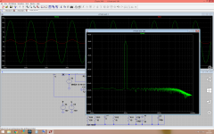
This is the final SIM from which I started to built new front-end for FO amp (this year's latest version). Reality was not as perfect as SIM, still lot of tweaks were needed, but anyway it was good starting point, also a little proof that my theoretical expectations were correct, at least in the right direction. So never give up, you'll find a sweet spot in your design eventually.
Attachments
this is profi 😀 is not that best on diyaudio?
..
what was load for that 500kHz square from previous post? I tried it with 8R
..
what was load for that 500kHz square from previous post? I tried it with 8R
This is the final SIM from which I started to built new front-end for FO amp (this year's latest version). Reality was not as perfect as SIM, still lot of tweaks were needed, but anyway it was good starting point, also a little proof that my theoretical expectations were correct, at least in the right direction. So never give up, you'll find a sweet spot in your design eventually.
Which amp is this, can you show the schmo?
Thanks
This is the final SIM from which I started to built new front-end for FO amp (this year's latest version). Reality was not as perfect as SIM, still lot of tweaks were needed, but anyway it was good starting point, also a little proof that my theoretical expectations were correct, at least in the right direction. So never give up, you'll find a sweet spot in your design eventually.
I suppose this is preamp looking at the gain.
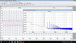
Here is simulated GW mk3 with boosted power supply to +-24 V.
Your simulation does not show anything below 120 dB, probably because simulation parameters are not set optimally. In that case harmonics are not visible. Here you can see harmonics but all are below 150 dB.
Attachments
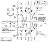
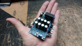
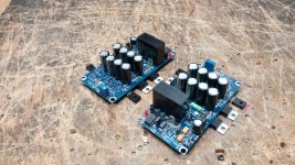
TC 1.0 v2
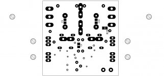
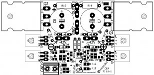
small update: TC_1.0_v2
- version with bigger output transistors 30MHz (FJL4215/FJL4315)
- improvement in few values (resistors for input transistors, VAS resistors)
- PCB remained small, in cheap size 5x5cm (gerbers included)
... sound is excellent
small update: TC_1.0_v2
- version with bigger output transistors 30MHz (FJL4215/FJL4315)
- improvement in few values (resistors for input transistors, VAS resistors)
- PCB remained small, in cheap size 5x5cm (gerbers included)
... sound is excellent
Attachments
-
TC_01_v2_pcb_bottom_mirror.pdf8.2 KB · Views: 146
-
TC_01_v2_pcb_top.pdf9 KB · Views: 169
-
 TC_01_v2_parts_bottom.jpg89.2 KB · Views: 643
 -
 TC_01_v2_parts_top.jpg227 KB · Views: 730
 -
 TC_01_v2_sch.jpg384.7 KB · Views: 723
 -
gerbers_TC_01_v2_elecrow.zip100.4 KB · Views: 130
-
TC_01_v2_BOM.zip5.4 KB · Views: 151
-
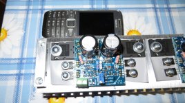 image003.jpg564.5 KB · Views: 342
 -
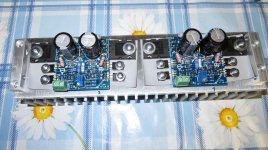 image002.jpg651.3 KB · Views: 397
 -
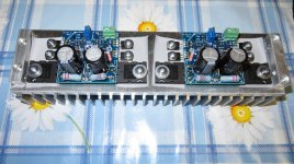 image001.jpg641.8 KB · Views: 393
it all depends on your preferences
if R5/R8=22k == cca. 15mA each output transistor (+-42V)
...
you can modify it with own preferences, if you need trimer and thermal stability than instead of D1/D2 you can add vbe multiplier, or you can place D1/D2 on heatsink (or use transistors with diode - like NJL3281D/NJL1302D)
if R5/R8=22k == cca. 15mA each output transistor (+-42V)
...
you can modify it with own preferences, if you need trimer and thermal stability than instead of D1/D2 you can add vbe multiplier, or you can place D1/D2 on heatsink (or use transistors with diode - like NJL3281D/NJL1302D)
This is the final SIM from which I started to built new front-end for FO amp (this year's latest version). Reality was not as perfect as SIM, still lot of tweaks were needed, but anyway it was good starting point, also a little proof that my theoretical expectations were correct, at least in the right direction. So never give up, you'll find a sweet spot in your design eventually.
http://www.diyaudio.com/forums/solid-state/318989-amnesis-amp-amplifier-gentleman-memory-4.html#post5373771
Just a classic CFA with a transistor used as a diode to equal DV voltages between input and feedback input ?What about this CFA concept from THS3001?
http://www.ti.com/lit/ds/symlink/ths3001.pdf
And what about input impedance ?
Is seems to me that Diamond do the same, adding some other advantages like gain in the input stage ...
Attachments
Last edited:
- input impedance is not big, I think about 150k?
- if diamond is doing the same, I dont know ... note that I am not a pro-designer, I am doing it just for fun ... and for sound impression 😀 😀 ... some pro designs were for me boring or disturbing in sound impression (with diamond), and this amateur thing kicked their *** ...
And what about linearity?
On my opinion (and, like you, I'm as much involved in the subjective sound qualities than pure technical results), it is a pity to loose the gain that can bring a transistor, using-it as a diode.
Diamonds will give-you a big amount of current gain, and isolate the input.
They, sometimes, are prone to very high frequencies ringing. You can cure-it, adding a resistance in serial to the base of the second stage as i showed. And, adding a capacitance to ground after this resistance, fix an input filter which will be independent from the source's impedance. This will ensure you will never overdrive the amp in speed (TIM) while keeping a very high slew rate. A tip: fix your Miller cap for no ringing at high levels, then this filter for no ringing with little signals. This will be the minimum value of the input filter. And the first stage of the diamond is out of the feedback loop.
An other tip, fix your Miller cap between the output of the amp and the base of your gain stage, instead of between its base and collector. You will decrease distortion, as the output stage has no problem to deliver as much current to charge this capacitance at HF than needed. Not the case at the collector.
Last edited:
With your point about diodes was possible to simplify this design even more 😀 😀 thanks for that 😀

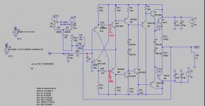
and here is working diamond input:

and here is working diamond input:
The problem with the simple diode, is that they don't exactly follow the voltage drop of the transistor. So, you add a risk of DC at the output, or ask too much from a servo. The original solution was better, I thinkWith your point about diodes was possible to simplify this design even more 😀 😀 thanks for that 😀
and here is working diamond input:
View attachment 675891
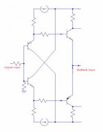
About Diamond: Your capacitance at input is not at the good place: charging the preamp that you don't know how he behave with a capacitance load.
See my quick'n dirty image.
Well, you'll have to reconsider too your compensation. Paralleling a cap with the feedback resistance is not recommended with current feedback amps.
And last, i thing the impedance of your feedback bridge is too high in front of the parasitic capacitance of Q9 Q10: you will loose bandwidth and add distortion.. Try something like 500 Ohms with ~23 Ohms as the feedback bridge ?
Attachments
Last edited:
I changed these values ... except feedback resistors, because with 500/23 it goes into oscillation 😀
cap in feedback with CFA amp is questionable, you can find right value with square simulation (bad/too big value can increase possibility of oscillation, too small value can do the same, right value can help) 😀
here is ltspice file if you like to simulate ...
cap in feedback with CFA amp is questionable, you can find right value with square simulation (bad/too big value can increase possibility of oscillation, too small value can do the same, right value can help) 😀
here is ltspice file if you like to simulate ...
Attachments
Last edited:
- Status
- Not open for further replies.
- Home
- Amplifiers
- Solid State
- Another very fast CFA concept