Good evening all
Following a recent house move I have been provided with a new opportunity to design some speakers to fit in a new space in the new house. Thanks to the new world we live in, one room upstairs has gained the honorable triple designation of guest room/Phil's office/music room.
Following a few ideas, including one that was discussed on this forum, I was pointed towards considering a line array solution. After a ton of reading, a bit of planning, some design work and a few mistakes along the way, I have a fairly robust concept (I think) which is now firmly into the production phase. Given the amount of support I have received from this community, both actively through feedback to previous posts and passively through reading other people's experiences, I thought it would be good to share my project and perhaps get some feedback.
The basis for the concept was driven by a couple of defining factors. The room will have a king size Murphy bed along one wall which would also be the prime location for audio equipment and speakers. Given the width of the Murphy bed, this does create a bit of a challenge in trying to not push the speakers too far apart. Secondly the speakers need to be very efficient as I have a pair of mono-block tube amps that output about 6W max. After contemplating a variety of single FR driver solutions, someone suggested investigating a line array solution. After a bit of research and comparison of 2-way design vs FR design, I decided to go with a FR line array concept given that I will be far enough away from the speakers to not have to worry about comb effect, and based on a few folks here who have had great success with FR line array concepts. After a bit of online research I also came to the conclusion that the best driver to start with as the basis of the design would be the TC9 from Tymphany, again based on others' success and the relatively low cost of the drivers.
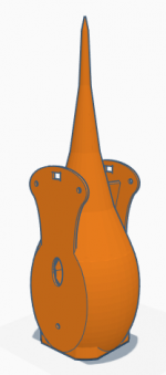
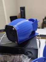
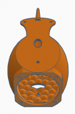
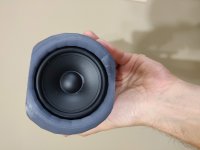
Given my wood working skills are pretty weak and I have recently gotten into 3D printing I decided to see if I could come up with a modular design for a line array. The basic idea was to create a 3D printed box for each driver that would be easily stack-able in any quantity desired to give a full line of drivers. For those that are not familiar with 3D printing techniques, flat surfaces and right angles can be challenging to print efficiently (read with using a ton of material) and the most robust (read strong) designs are often curved in nature. After looking around for some inspiration I was drawn to the B&W Nautilus design and set about seeing if I could create some sort of facsimile.
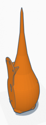
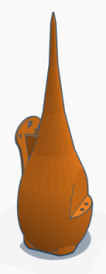
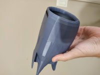
My initial concept was what I would describe as a tadpole. A driver mounted to a spherical box, linked to a elongated conical tail, stretched out as long as my print capacity would allow. In order to make this design stack able, I then applied a flat edge to the top and bottom of the spherical area at the same width as the driver which would also allow the drivers from adjacent units to be as close together as possible to reduce comb effect as much as possible.
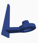
The next step was to create a wing to provide more depth to the interface plane between 2 adjacent boxes to provide more structural stability as the line is put together. Into the wings I added 2 6mm holes to allow adjacent units to be bolted together and an interface point for the stand clips (more on that below).
Inside the box I created a single 6mm hole near the front of the flat side to provide a forward bolting point for adjacent units. I also created 2 oval shaped holes in perpendicular planes with one located towards the front of the box and one towards the back. The purpose of these holes is to provide some leakage between adjacent units, but also to allow wiring runs between units. By offsetting the holes from each other I hope to avoid creating a single large vertical chamber through all the vertically stacked drivers.
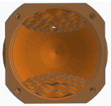
The final internal design element was to place a pattern of irregularly spaced shallow cones in the inside of each of the flat surfaces on the top and bottom of the unit. The cones are intended to ensure there are minimal parallel surfaces internally, thus reducing the risk of standing waves inside the box. The pattern of cones also has the nice side effect of making the flat side of the box thicker and thus stronger and more resistant to vibration. The rounded elements both in the spherical box and the tail are proving phenomenally strong at even just a few millimetres of thickness when printed with standard PLA type materials.
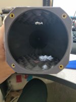
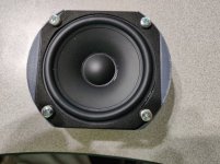
On the front face of the box I put holes to allow knurled threaded inserts to be placed and then heated so they would melt slightly into the plastic and provide an anchor point for the driver screws.
The finalized box design has an internal volume of approximately 1 liter (measured by filling one up with water) and each box will be liberally stuffed with polyfill.
I am creating a driver flange seal from 1/16" neoprene to be mounted between the driver and the box, to try to help reduce vibration transmission from the driver cage to the box and vice versa. I intend to place a thin layer of clear silicone between the units as I begin to stack them up to both help with stability and again attempt to reduce any potential vibration propagation between units as far as possible. I did consider some more exotic acoustic treatment for between the boxes like Decidamp DC30, but found it hard to come by, and not sure I need that much damping between the boxes.
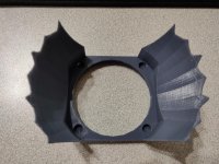
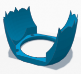
The final design element is a mount to allow me to attach the arrays to the sides of the Murphy bed. The relatively simple design interfaces with the back of the winged section via 2 raised triangular raised surfaces that click in to the holes created on the wings. This provides a sturdy interface yet there is enough flexibility in the wings to remove the box from the stand if required. I have yet to test this design with the weight of multiple boxes, but for my 25 driver array I intend to have 6 mounts.
My wiring plans at this moment are simply 5 groups of 5 drivers in series. I do not intend to do any power shaping as I have seen good feedback from others that have not done this.
I have also taken all the relevant design principles and created a single box solution to allow me to put 1 driver in a box of broadly the same design to check the performance. Now I will say I have not done any formal measurements, but the single box with 1x $9 driver in it, playing summed mono output actually sounded really good. Obviously lacking in bottom end but I do plan to build some sub woofers to support the lower end once the arrays are complete.
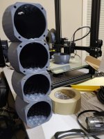
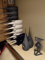
So that's my journey so far. Each speaker box takes roughly 28 hours to print and so far I have only produced 4 of the 50 I will need, so it will be some time before I get the project complete. My next real world test plan is to get an array of 7 drivers put together and see how they sound.
If anyone has any questions, comments, suggestions, or ideas please let me know. I will attach some pictures of my design files and progress to date, and will look to keep updating this thread as I make further progress.
Phil
Following a recent house move I have been provided with a new opportunity to design some speakers to fit in a new space in the new house. Thanks to the new world we live in, one room upstairs has gained the honorable triple designation of guest room/Phil's office/music room.
Following a few ideas, including one that was discussed on this forum, I was pointed towards considering a line array solution. After a ton of reading, a bit of planning, some design work and a few mistakes along the way, I have a fairly robust concept (I think) which is now firmly into the production phase. Given the amount of support I have received from this community, both actively through feedback to previous posts and passively through reading other people's experiences, I thought it would be good to share my project and perhaps get some feedback.
The basis for the concept was driven by a couple of defining factors. The room will have a king size Murphy bed along one wall which would also be the prime location for audio equipment and speakers. Given the width of the Murphy bed, this does create a bit of a challenge in trying to not push the speakers too far apart. Secondly the speakers need to be very efficient as I have a pair of mono-block tube amps that output about 6W max. After contemplating a variety of single FR driver solutions, someone suggested investigating a line array solution. After a bit of research and comparison of 2-way design vs FR design, I decided to go with a FR line array concept given that I will be far enough away from the speakers to not have to worry about comb effect, and based on a few folks here who have had great success with FR line array concepts. After a bit of online research I also came to the conclusion that the best driver to start with as the basis of the design would be the TC9 from Tymphany, again based on others' success and the relatively low cost of the drivers.
Given my wood working skills are pretty weak and I have recently gotten into 3D printing I decided to see if I could come up with a modular design for a line array. The basic idea was to create a 3D printed box for each driver that would be easily stack-able in any quantity desired to give a full line of drivers. For those that are not familiar with 3D printing techniques, flat surfaces and right angles can be challenging to print efficiently (read with using a ton of material) and the most robust (read strong) designs are often curved in nature. After looking around for some inspiration I was drawn to the B&W Nautilus design and set about seeing if I could create some sort of facsimile.
My initial concept was what I would describe as a tadpole. A driver mounted to a spherical box, linked to a elongated conical tail, stretched out as long as my print capacity would allow. In order to make this design stack able, I then applied a flat edge to the top and bottom of the spherical area at the same width as the driver which would also allow the drivers from adjacent units to be as close together as possible to reduce comb effect as much as possible.
The next step was to create a wing to provide more depth to the interface plane between 2 adjacent boxes to provide more structural stability as the line is put together. Into the wings I added 2 6mm holes to allow adjacent units to be bolted together and an interface point for the stand clips (more on that below).
Inside the box I created a single 6mm hole near the front of the flat side to provide a forward bolting point for adjacent units. I also created 2 oval shaped holes in perpendicular planes with one located towards the front of the box and one towards the back. The purpose of these holes is to provide some leakage between adjacent units, but also to allow wiring runs between units. By offsetting the holes from each other I hope to avoid creating a single large vertical chamber through all the vertically stacked drivers.
The final internal design element was to place a pattern of irregularly spaced shallow cones in the inside of each of the flat surfaces on the top and bottom of the unit. The cones are intended to ensure there are minimal parallel surfaces internally, thus reducing the risk of standing waves inside the box. The pattern of cones also has the nice side effect of making the flat side of the box thicker and thus stronger and more resistant to vibration. The rounded elements both in the spherical box and the tail are proving phenomenally strong at even just a few millimetres of thickness when printed with standard PLA type materials.
On the front face of the box I put holes to allow knurled threaded inserts to be placed and then heated so they would melt slightly into the plastic and provide an anchor point for the driver screws.
The finalized box design has an internal volume of approximately 1 liter (measured by filling one up with water) and each box will be liberally stuffed with polyfill.
I am creating a driver flange seal from 1/16" neoprene to be mounted between the driver and the box, to try to help reduce vibration transmission from the driver cage to the box and vice versa. I intend to place a thin layer of clear silicone between the units as I begin to stack them up to both help with stability and again attempt to reduce any potential vibration propagation between units as far as possible. I did consider some more exotic acoustic treatment for between the boxes like Decidamp DC30, but found it hard to come by, and not sure I need that much damping between the boxes.
The final design element is a mount to allow me to attach the arrays to the sides of the Murphy bed. The relatively simple design interfaces with the back of the winged section via 2 raised triangular raised surfaces that click in to the holes created on the wings. This provides a sturdy interface yet there is enough flexibility in the wings to remove the box from the stand if required. I have yet to test this design with the weight of multiple boxes, but for my 25 driver array I intend to have 6 mounts.
My wiring plans at this moment are simply 5 groups of 5 drivers in series. I do not intend to do any power shaping as I have seen good feedback from others that have not done this.
I have also taken all the relevant design principles and created a single box solution to allow me to put 1 driver in a box of broadly the same design to check the performance. Now I will say I have not done any formal measurements, but the single box with 1x $9 driver in it, playing summed mono output actually sounded really good. Obviously lacking in bottom end but I do plan to build some sub woofers to support the lower end once the arrays are complete.
So that's my journey so far. Each speaker box takes roughly 28 hours to print and so far I have only produced 4 of the 50 I will need, so it will be some time before I get the project complete. My next real world test plan is to get an array of 7 drivers put together and see how they sound.
If anyone has any questions, comments, suggestions, or ideas please let me know. I will attach some pictures of my design files and progress to date, and will look to keep updating this thread as I make further progress.
Phil
Attachments
-
 Line Array Module 1.PNG20.5 KB · Views: 642
 -
 IMG_20201016_205616.jpg395.4 KB · Views: 291
 -
 IMG_20201016_224125.jpg358.9 KB · Views: 279
 -
 IMG_20201016_224006.jpg384.9 KB · Views: 268
 -
 IMG_20201016_205607.jpg350.5 KB · Views: 246
 -
 Line Array Module Stand.PNG14.9 KB · Views: 184
 -
 Line Array Module Top.PNG21.1 KB · Views: 642
 -
 Line Array Module Bottom.PNG21.9 KB · Views: 612
 -
 Line Array Module 3.PNG96.9 KB · Views: 618
 -
 Line Array Module 2.PNG24.4 KB · Views: 635

Original, to say the least!
It will be interesting to see how your 6w amp will fare. Most line array users are sending a lot more power to their towers.
You didn't mention about upstream, as I'm sure you read during your research that LA need EQ.
Will be looking for updates.
Good luck.
It will be interesting to see how your 6w amp will fare. Most line array users are sending a lot more power to their towers.
You didn't mention about upstream, as I'm sure you read during your research that LA need EQ.
Will be looking for updates.
Good luck.
Finally someone that uses the flexibility of 3D printing. All too often we see rectangular shapes for 3D prints, while the whole concept of printing offers so much more!
I would have loved it even more if you had used the shape to extend the driver face to a rounding shape to reduce diffraction, just on the sides. That's what B&W did after all 😉.
Be sure to seal the PLA with something if there is a chance of the enclosures catching sunlight. PLA tends to get brittle over time when exposed to sunlight, though the more recent filaments do way better than the ones from a few years back.
We used 3D printers at work (for fun and learning), we started with a 3D printed printer (all constructional parts were printed) and were continuously printing printer parts, just to keep it running 😀.
One more thing also mentioned by perceval, you're going to need some form of EQ, be it passive or active, to balance out the frequency response of that many drivers in an array. Any plans for that yet? You could do it passively, as there are plans in place to support the bottom end.
6 Watt of power 🙂, quite a bit different from my 350 watt (lol). Still it should work, considering the jump in output of an array.
Thanks for all the quick responses. Glad to have piqued some interest.
As far the the upstream electronics, today I have 2 main sources, an Audio-Technica turntable which is probably used less than 5% of the time, and a Chromecast Audio that use to stream either from my library of lossless files, or much more frequently from Tidal. The Chromecast is connected via optical cable to a Parasound P5 preamp. Full range output is sent to a pair of Bottlehead MonAmour SET power amps, and a low-passed signal is sent to a separate sub that I have to fill in the very bottom end.
I have been reading a lot about the need for EQ from the various projects here so do have that in mind. My current plan to to get hold of the Behringer DEQ2496 and tackle the EQ in the digital domain between the sources and the preamp. It seems like a fairly capable unit that is available here for just a few hundred dollars which is in my realm of affordability. I figure I can at least start there and see if I need to go more extravagant.
It does mean the output from the turntable will need to get processed in the digital domain for now, which kind of defeats the whole point of an analog signal path, but I figure if I get on well then perhaps down the line I can investigate an analog EQ if I find it really bothersome.
Wesayso - Firstly let me just say how much I appreciate the information you have shared throughout your journey. I have read quite a bit of your Two Towers thread, though not admittedly not all, there's a lot of info there.
Secondly, I had not actually considered sealing the units at all. Having read your comment and looked around on the internet it definitely seems like it would be a worthwhile endeavor given the amount of effort going into the project overall. As you seem to have some experience here is there anything you would recommend. I would like to keep the sealing layer as thin as possible as some of the tolerances for the interfaces are fairly tight. I see a lot of recommendations for epoxy but most of those seem to be about print smoothing or water proofing, neither of which really bother me.
Will have to do some more research but any experiences that can be shared would be appreciated.
Thirdly, you have got me thinking now regarding the driver interface. You are absolutely right on the B&W concept. Frankly the challenge I have had is fitting a square peg into a round hole. If I understand your suggestion, you are saying to effectively push the driver further back into the box, and effectively create a circular baffle from PLA with the driver front flush rather than protruding. I am going to play with some designs, but I think that should be fairly doable.
ggetzoff - I like the Babel fish reference. I have been thinking how best to describe the project and I think you just nailed it.
I tried to look up what the problem might have been, that we used to have with our 3D printed construction. At first i thought it was direct sunlight, but it turns out the heat from the printer standing behind a window might have caused it. (we did have sun screens but they weren't down on weekends)
See: How Long Will a PLA 3D Printed Object Last? - 3dPrinterGeeks.com
We used to have an old classroom in a 20's/30's building where it could get quite hot during summers. So that might explain what we observed. The objects would indeed discolor and get brittle. My impression is that the filament materials did improve over time, but it will always be a biodegradable material. If we left the printer overnight with the filament still loaded into its bowden tube, we often found the filament string had snapped overnight.
In a later building we had a very different room, no direct sunlight and air conditioned, we have never had that happen again. But as said, the early filaments we used weren't of great quality. These days we settle on certain brands we liked most, like Formfutura or Colorfabb. Good quality filament and most important very consistent thickness of the filament which makes the printing job consistent in quality too.
I guess nothing can stop that degradation process, one can only slow it down by keeping it cool, so it seems. So sealing it might not be that useful after all. Epoxy often is used to seal prints, indeed for making them waterproof. A polyurethane paint should work too. Making sure it isn't exposed to heat seems to be the best way to preserve it though. I hope your room temperature is pretty constant throughout the year!
PETG might be a good alternative, I guess that would be more durable than PLA.
How To Print PETG Filament 2020 - [Step by Step + Settings]
About the shape, a rounded shape on the outside, indeed starting at the driver frame would help lesen any diffraction.
In my own speakers I tried to make the enclosure flow in an as smooth a shape as I could envision from the cone outward (hindered only by the surround):

Round-overs do work (bigger = better), but we have to stop somewhere, don't we 😀.
See: How Long Will a PLA 3D Printed Object Last? - 3dPrinterGeeks.com
We used to have an old classroom in a 20's/30's building where it could get quite hot during summers. So that might explain what we observed. The objects would indeed discolor and get brittle. My impression is that the filament materials did improve over time, but it will always be a biodegradable material. If we left the printer overnight with the filament still loaded into its bowden tube, we often found the filament string had snapped overnight.
In a later building we had a very different room, no direct sunlight and air conditioned, we have never had that happen again. But as said, the early filaments we used weren't of great quality. These days we settle on certain brands we liked most, like Formfutura or Colorfabb. Good quality filament and most important very consistent thickness of the filament which makes the printing job consistent in quality too.
I guess nothing can stop that degradation process, one can only slow it down by keeping it cool, so it seems. So sealing it might not be that useful after all. Epoxy often is used to seal prints, indeed for making them waterproof. A polyurethane paint should work too. Making sure it isn't exposed to heat seems to be the best way to preserve it though. I hope your room temperature is pretty constant throughout the year!
PETG might be a good alternative, I guess that would be more durable than PLA.
How To Print PETG Filament 2020 - [Step by Step + Settings]
About the shape, a rounded shape on the outside, indeed starting at the driver frame would help lesen any diffraction.
In my own speakers I tried to make the enclosure flow in an as smooth a shape as I could envision from the cone outward (hindered only by the surround):
Round-overs do work (bigger = better), but we have to stop somewhere, don't we 😀.
Last edited:
OK that picture really helped. I have attached some pictures of my first go at changing the driver interface based on your feedback and am already much happier with the result, both in terms of the interface and the finished aesthetics.
However based on your diagram I think I can take it a step further and create a 2 piece solution to get something similar to your design and create a smooth curve all the way from the cone.
Will have to do some more tinkering with the design tomorrow.
With regards the room temperature and the sealing, I live in Houston in a house with whole home AC that is kept in a pretty tight window all year (I can be a bit finicky about the right temperature myself) so don't expect that to be an issue. But may do some more reading a go ahead and seal anyway. When I was doing my volume checks I noticed the enclosure wasn't watertight, particularly where the tail gets thinner towards the end. Not sure if the enclosure needs to be completely sealed, but I'm sure it wouldn't do any harm for longevity.
Attachments
Evening all
Few quick updates.
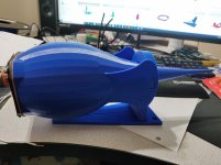
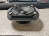
Following feedback from wesayso I decided to look into a way to redesign the front of the speaker box to create a more smoothed/curved transition from the driver cone to the outside of the box. After playing around with a few options I settled on a facia piece that will get installed over the top of my original box design. This not only provides a much better transition from the cone, but also covers the mounting hardware and I think much improves the overall aesthetics.
I think at this stage I will likely need to use something like silicone or epoxy to bind the 2 pieces, which will make the build a one way journey. I do also intend to experiment with the use of epoxy to smooth the surface of the facia plate even more.
One other unfortunate downside is the facia takes about 6 hours to print so I have just added another 300 hours to my print queue.
Other than that, I may do some research on different 3D printing materials as there is quite an exotic range of materials available now, each with different physical properties. I am thinking that given the proximity of the facia to the driver cone it may have some ability to influence the sound produced depending on the properties of the material used.
If nothing else it will give me an excuse to experiment with a bunch of different printing materials.
Currently printing driver box number 7 of 50. I hope to get a mock up of a 7 driver array (minus the facias) set up in the next week or so and just see what it is like.
Phil
Few quick updates.
Following feedback from wesayso I decided to look into a way to redesign the front of the speaker box to create a more smoothed/curved transition from the driver cone to the outside of the box. After playing around with a few options I settled on a facia piece that will get installed over the top of my original box design. This not only provides a much better transition from the cone, but also covers the mounting hardware and I think much improves the overall aesthetics.
I think at this stage I will likely need to use something like silicone or epoxy to bind the 2 pieces, which will make the build a one way journey. I do also intend to experiment with the use of epoxy to smooth the surface of the facia plate even more.
One other unfortunate downside is the facia takes about 6 hours to print so I have just added another 300 hours to my print queue.
Other than that, I may do some research on different 3D printing materials as there is quite an exotic range of materials available now, each with different physical properties. I am thinking that given the proximity of the facia to the driver cone it may have some ability to influence the sound produced depending on the properties of the material used.
If nothing else it will give me an excuse to experiment with a bunch of different printing materials.
Currently printing driver box number 7 of 50. I hope to get a mock up of a 7 driver array (minus the facias) set up in the next week or so and just see what it is like.
Phil
Attachments

Last edited:
Evening All
Been a couple of weeks since my last update so wanted to share my latest progress and design evolution tweaks.
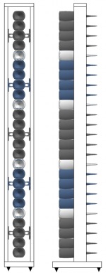
I have now completed printing 17 of the 50 modules required for my pair of speakers. I have sourced all the required printing filament and made some design decisions, choosing to go with a design based on 3 colors, grey, white and blue.
I have also sourced all the speaker drivers to complete the build and all the hardware and electrical supplies to complete the build.
Since my last update I tried printing one of the driver fascia pieces in a different material (PETG) to see how it would react. I found the result to be less pleasing with a less precise print, especially in the more fine details, as well as a notably more flexible final piece. After toying with differing materials and color options I have decided to make the fascia pieces out of the same material and color as the main modules. I have also decided that I am going to defer this part of the project until the end as I should be able to simply slide these into place once the lines are built.
I have also done some experimenting with epoxy coatings. I do intend to ultimately coat the entire line to provide a layer of additional protection against the long term breakdown of the plastic, but again I have decided to defer this activity until the line is built in it's entirety.
I have also done a lot of research on bonding solutions to adhere the driver boxes to each other to increase the overall structural strength of the line. The solution I have settled on is to use acetone bonding. Essentially a thin application of acetone is applied to both of the pieces to be bonded, which has the effect of melting the very top layer of plastic where it is applied. By quickly pressing the pieces together and holding with some pressure, you can essentially weld the 2 pieces together as the acetone evaporates out, creating a very strong bond with very little additional material added between the layers. I do still intend to utilize mechanical fasteners to hold the driver boxes together but now it will be more about maintaining pressure while the acetone bonding cures.
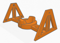
The biggest change since my last update is in the overall mounting solution. Originally I had planned to mount the entire line to the edge of a murphy bed that will be in the room. I have now decided to construct a simple speaker stand to mount the line too. I have designed a speaker mount with 2 mounting points which will provide rigidity to the speaker stand from the line as well as support the weight of the line. This option will allow me to move speakers in the space giving me much more flexibility (along with an active EQ) to dial in the performance.
I had also planned to put together a 7 driver line for testing purposes. At this point I am going to hold off from that and simply go straight to building a single speaker line before I do any testing of overall performance.
One final note, I was able to find a new control board for my 3d printer. As delivered, the printer made constant noise from the motors as the printer moved the extruder. It wasn't terrible, but had an earworm quality that you would continue hearing even after leaving the room. The new control board has almost completely silenced my printer meaning I can crack on 24/7. With my components pretty much finalized, the speaker boxes are taking approximately 28 hours each, the speaker mount takes about 10 hours. My current conservative estimate is I have approximately 1014 hours of printing to go. If I can maintain a 90% uptime for my printer (which is fairly aggressive) I should be done with printing the boxes and mounts for both speakers right around Dec 20th.
I have attached a few pictures of the new speaker mount design (kind of like a tie fighter) and some rough mockup's of what I expect the final unit to look like.
As always, any comments, questions or thoughts are welcome and appreciated.
Phil
Been a couple of weeks since my last update so wanted to share my latest progress and design evolution tweaks.
I have now completed printing 17 of the 50 modules required for my pair of speakers. I have sourced all the required printing filament and made some design decisions, choosing to go with a design based on 3 colors, grey, white and blue.
I have also sourced all the speaker drivers to complete the build and all the hardware and electrical supplies to complete the build.
Since my last update I tried printing one of the driver fascia pieces in a different material (PETG) to see how it would react. I found the result to be less pleasing with a less precise print, especially in the more fine details, as well as a notably more flexible final piece. After toying with differing materials and color options I have decided to make the fascia pieces out of the same material and color as the main modules. I have also decided that I am going to defer this part of the project until the end as I should be able to simply slide these into place once the lines are built.
I have also done some experimenting with epoxy coatings. I do intend to ultimately coat the entire line to provide a layer of additional protection against the long term breakdown of the plastic, but again I have decided to defer this activity until the line is built in it's entirety.
I have also done a lot of research on bonding solutions to adhere the driver boxes to each other to increase the overall structural strength of the line. The solution I have settled on is to use acetone bonding. Essentially a thin application of acetone is applied to both of the pieces to be bonded, which has the effect of melting the very top layer of plastic where it is applied. By quickly pressing the pieces together and holding with some pressure, you can essentially weld the 2 pieces together as the acetone evaporates out, creating a very strong bond with very little additional material added between the layers. I do still intend to utilize mechanical fasteners to hold the driver boxes together but now it will be more about maintaining pressure while the acetone bonding cures.
The biggest change since my last update is in the overall mounting solution. Originally I had planned to mount the entire line to the edge of a murphy bed that will be in the room. I have now decided to construct a simple speaker stand to mount the line too. I have designed a speaker mount with 2 mounting points which will provide rigidity to the speaker stand from the line as well as support the weight of the line. This option will allow me to move speakers in the space giving me much more flexibility (along with an active EQ) to dial in the performance.
I had also planned to put together a 7 driver line for testing purposes. At this point I am going to hold off from that and simply go straight to building a single speaker line before I do any testing of overall performance.
One final note, I was able to find a new control board for my 3d printer. As delivered, the printer made constant noise from the motors as the printer moved the extruder. It wasn't terrible, but had an earworm quality that you would continue hearing even after leaving the room. The new control board has almost completely silenced my printer meaning I can crack on 24/7. With my components pretty much finalized, the speaker boxes are taking approximately 28 hours each, the speaker mount takes about 10 hours. My current conservative estimate is I have approximately 1014 hours of printing to go. If I can maintain a 90% uptime for my printer (which is fairly aggressive) I should be done with printing the boxes and mounts for both speakers right around Dec 20th.
I have attached a few pictures of the new speaker mount design (kind of like a tie fighter) and some rough mockup's of what I expect the final unit to look like.
As always, any comments, questions or thoughts are welcome and appreciated.
Phil
Attachments

Some interesting choices we make this days Phil. My home studio tracking room doubles as a spare bedroom with a queen Murphy bed! ......the door panels are a combo design of bass trapping using the mattress and diffusion slots.......along with some other acoustic modest acoustic treatments, this room sounds amazing with vocals and drums.
I’ve always used DIY as a tool to adapt my environment to devices such as end table subwoofers and wall hanging speaker art.......look fwd to what you come up in this design......the enclosures look great!
I’ve always used DIY as a tool to adapt my environment to devices such as end table subwoofers and wall hanging speaker art.......look fwd to what you come up in this design......the enclosures look great!
I am not sure my wife would appreciate me taking a hacksaw to our new murphy bed for the purpose of bass management, though I will say I applaud the ingenuity and commitment.
I am actually trying my hardest to not get sucked into thinking about bass augmentation. I have a decent enough sub which I can use for now, but I have been considering all sorts of outlandish subwoofer solutions from a bunch of relatively small sealed boxes spread around the room to a massive TL type sub mounted above the murphy bed cabinet.
I do also have room treatments in mind. As this room is predominantly my space I think I will have a bit more leeway with placement of treatments based on measurements rather than trying to maintain a particular aesthetic.
One crazy project at a time I think.
Hope you have a big box of popcorn Drengur, it may be a while yet! 🙂
Evening All
Quick update on progress. Just finished up box number 25. Unfortunately not quite the right configuration for one whole speaker but getting close. Primary build schedule for speaker boxes and mounts has slipped to about the 22nd Dec.
I have managed to find a hefty piece of wood that I can utilize for the base for the speakers onto which I will build the lines up. My in-laws have a renovation company and had a mantle piece that never got installed. It is 4" thick and about 11" wide by 48" long. My intention to to cut 2 pieces 18" long to serve as the base giving me some significant weight to help with stability as much as possible.
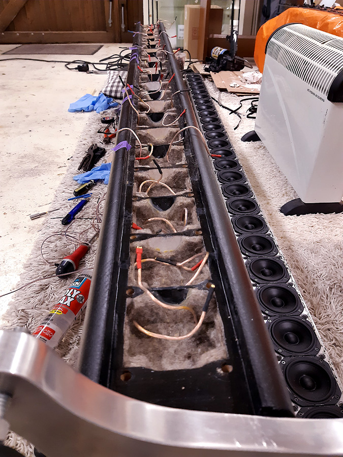
I am not starting to look at wiring. I was initially planning to wire the line as 5 parallel groups of 5 speakers in series. This would yield a line with equal output across it's entire length which I know from reading, others have done with success.
However I have looked into power tapering, particularly as a function of changing the numbers of drivers in each group to vary the output of each driver in relation to drivers in other groups, thereby creating a power tapering effect.
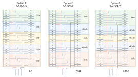
After a bit of tinkering with some math I think I have the 3 most viable options. Option 1 in the attached is the base case. Option 2 and 3 increase the number of drivers in the top and bottom groups such that groups with smaller quantities of driver will receive an effective output boost. I wasn't really sure how to calculate the effect, but after reading online took the approach that each of the paralleled groups of drivers will receive an equivalent voltage at the primary connection points. This voltage can then be divided by the number of series'd drivers in each group to give the relative voltage across a single driver in the group. By comparing the voltage across a driver in each of the 5 groups I can therefore calculate the effective gain for the boosted groups using the drivers with the lowest output as a reference point.
The theory makes sense, but it would be great if someone with more experience could confirm that I am not way off base on my assumptions.
Based on my assumptions you can see the effective gain for each of the groups in the attached pic.
In Option 2 the center group is boosted by 6db above the outer most group with the linking groups boosted by 1.6db. My initial thought is that might be a bit too spikey in the middle of the line.
In Option 3 the center group is boosted by 7.3db above the outer most group with the linking groups boosted 4.9db. That feels a bit better in terms of widening the curve, but I am not sure if 7.3db and 4.9db is way too much gain, essentially negating the whole point of having a full floor to ceiling line.
Anyway, lots of good theory here, but I honestly do not have a good feel for what the impact of these variances might be. I think my current plan is to ensure that all of the paralleled links (the red and black wires in the diagram) are run long enough to allow me to try each configuration without having to cut and replace wires up and down the whole line.
Any thoughts or experience to share here would be greatly appreciated as always.
Phil
Quick update on progress. Just finished up box number 25. Unfortunately not quite the right configuration for one whole speaker but getting close. Primary build schedule for speaker boxes and mounts has slipped to about the 22nd Dec.
I have managed to find a hefty piece of wood that I can utilize for the base for the speakers onto which I will build the lines up. My in-laws have a renovation company and had a mantle piece that never got installed. It is 4" thick and about 11" wide by 48" long. My intention to to cut 2 pieces 18" long to serve as the base giving me some significant weight to help with stability as much as possible.
I am not starting to look at wiring. I was initially planning to wire the line as 5 parallel groups of 5 speakers in series. This would yield a line with equal output across it's entire length which I know from reading, others have done with success.
However I have looked into power tapering, particularly as a function of changing the numbers of drivers in each group to vary the output of each driver in relation to drivers in other groups, thereby creating a power tapering effect.
After a bit of tinkering with some math I think I have the 3 most viable options. Option 1 in the attached is the base case. Option 2 and 3 increase the number of drivers in the top and bottom groups such that groups with smaller quantities of driver will receive an effective output boost. I wasn't really sure how to calculate the effect, but after reading online took the approach that each of the paralleled groups of drivers will receive an equivalent voltage at the primary connection points. This voltage can then be divided by the number of series'd drivers in each group to give the relative voltage across a single driver in the group. By comparing the voltage across a driver in each of the 5 groups I can therefore calculate the effective gain for the boosted groups using the drivers with the lowest output as a reference point.
The theory makes sense, but it would be great if someone with more experience could confirm that I am not way off base on my assumptions.
Based on my assumptions you can see the effective gain for each of the groups in the attached pic.
In Option 2 the center group is boosted by 6db above the outer most group with the linking groups boosted by 1.6db. My initial thought is that might be a bit too spikey in the middle of the line.
In Option 3 the center group is boosted by 7.3db above the outer most group with the linking groups boosted 4.9db. That feels a bit better in terms of widening the curve, but I am not sure if 7.3db and 4.9db is way too much gain, essentially negating the whole point of having a full floor to ceiling line.
Anyway, lots of good theory here, but I honestly do not have a good feel for what the impact of these variances might be. I think my current plan is to ensure that all of the paralleled links (the red and black wires in the diagram) are run long enough to allow me to try each configuration without having to cut and replace wires up and down the whole line.
Any thoughts or experience to share here would be greatly appreciated as always.
Phil
Attachments
I recommend you do frequency tapering instead of power tapering. You want all the drivers 100% for the lowest notes.
If you look into Jack's thread (nc535) you can find a complete Vituixcad project of a 25 driver line array. That would make it possible to run some sims with the wiring you came up with before committing to anything.
See: https://www.diyaudio.com/forums/full-range/337956-range-line-array-wall-corner-placement-55.html#post6205129
(this one probably still has the floor reflection modeled as a separate array, you can delete that and re-arrange drivers at will and adjust the height numbers to that of your own array)
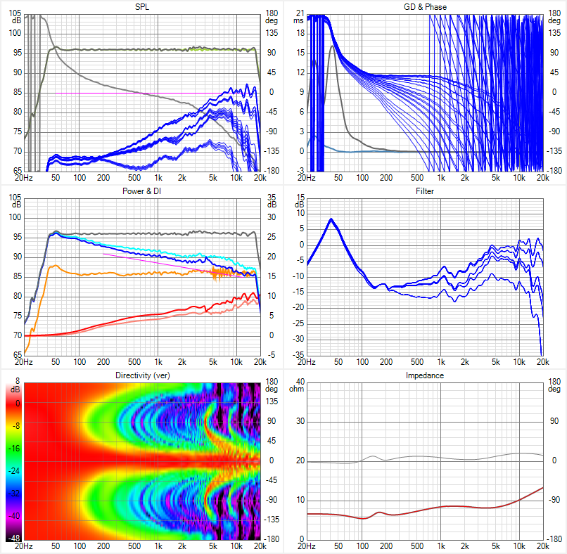
Personally I did not want to give up bottom extension and chose to experiment with frequency dependent shading. I'm currently rewiring my arrays to incorporate this type of shading:
Based on this sim:
But that Vituixcad project made by nc535 is easy to turn into your own virtual lab to test any plans you may have. I'd highly advise you to play with it and see what it does before picking any such schematic.
See: https://www.diyaudio.com/forums/full-range/337956-range-line-array-wall-corner-placement-55.html#post6205129
(this one probably still has the floor reflection modeled as a separate array, you can delete that and re-arrange drivers at will and adjust the height numbers to that of your own array)
Personally I did not want to give up bottom extension and chose to experiment with frequency dependent shading. I'm currently rewiring my arrays to incorporate this type of shading:
Based on this sim:
But that Vituixcad project made by nc535 is easy to turn into your own virtual lab to test any plans you may have. I'd highly advise you to play with it and see what it does before picking any such schematic.
Every time I think I have got this project figured out and I have a sight of the finish line, I learn something new.
Been reading the thread you linked and have downloaded VituixCAD and started playing with some simulations. I think the idea absolutely makes sense, especially given the amplifier I intend to use is pretty low power, but I'll be honest, at this point most of the concepts are way over my head. Looks like I have a lot of reading to do about how to apply components to create frequency filters and understand that impact of the changes being made.
I guess as a broad concept, the target is to reduce the frequency range going to the drivers on the extremity of the line by effectively created a passive low pass filter applied to the relevant groups of drivers.
Appreciate the pointers. I'm going to start by getting to grips with some fundamentals of using inductors and resistors to create frequency filters in the most lay-man terms I can find. Luckily I still have a ton of printing ahead of me so I have some time to learn.
Last edited:
You could be off to a running start, as there are a lot of schematics posted in that thread, as well as in my own thread. The important thing to do is make sure all dimensions used in Vituixcad agree with your own array. Plus you've got to determine how to group the drivers if you have a preference for a specific listening height.
What I tried to optimize is my listening height and all heights above and below that by +/- 100 mm. That's why my on axis plot is still a bit wiggly. This particular choice determined the components I needed. Extra care was put to make the standing height perform at least reasonable, it doesn't have to be as great as the optimized result but it should be bearable. Those were the starting points for me. If all you want is an optimized seated position your choices might be different.
I took another look at your stand, posted one page ago. A well meant warning from me, something like that could cause diffraction as you created a pair of parallel ridges to the drivers. Personally I try to avoid or treat (with absorption) parallel planes and/or ridges.Ideally I would try to make the stand less wide than the front surface of the baffle to avoid any and all waves from bouncing back. That's why my speaker has that sort of egg shape. A continuous flowing outer rim.
One more thing if I may, I try to set deadlines to, however it comes as it goes because life can be unpredictable. One thing I did learn from my project is patience. I'd rather do it well, once, and take my time than to rush something and be finished sooner (but not quite pleased with the outcome). 🙂
Important disclaimer:
Just take what I just typed as (well meant) advise from just another Audio 'idiot', because that's all I am. You think about it and decide what you want to do with it. Or even ignore me completely, you do have that right 😀. I'm just typing my thoughts, but that's what they are... thoughts. You decide what to do with it, not me.
Wesayso
Firstly let me address your disclaimer. I am frankly honored that you take time to read my story and provide your thoughts. You are among the few that really inspired me to give this whole DIY line array a go. The fact that you and others like you have taken so much time to document not only the project concept and results but also the journey you have taken along the way has really helped me to understand the process and guide some of the decisions I have taken. I fully respect that any comments made are simply thoughts and perspective, but I absolutely welcome you (and anyone else in this community) to share those thoughts, and I will always endeavor to receive them with an open mind.
Hopefully my efforts to document my journey on this site may help some future folks. Even if it ends up being a tale of "don't do what that guy did!"
With regards your other feedback, I read through some of the thread with you and nc535 discussing your simulations and tweaks and there is a ton of good information in there that I can use to get going with my understanding. However I have already started finding some online reading of fundamental theory (RL vs RC filters for example) as I am keen to understand why the things you guys do have the effect they have in the simulation, especially so when it comes to real world testing, I may have half a chance of identifying the cause of any variances from simulated responses. One of the points you raised was already on my mind in terms of the listening height that the line will be optimized for. I think I am going to simply my design and focus on a seated listening position rather than attempt to get an increased focal area like you are attempting to manage. But these are decisions I can take later in the process once I am more up to speed with the electrical design side of the process.
With regards my timeline, it's not so much a deadline as a milestone. I found that the epic mountain of 3D printing was starting to take on an element of negativity in my mind because there is simply so much to do. I decided that creating a production schedule and at least having a line of sight to a few milestones along the way may help keep the task from becoming overwhelming. I fully expect there to be several more steps along the way and am a realist when it comes to timelines. Honestly for me, the fun is more often in the journey than the result, but it is still nice to be able to set and track milestones along the way.
Finally to the most important point you raised. I cannot believe I didn't see the parallel structure of the supports in the stand concept until you flagged it. After spending so much time trying to mitigate parallel surfaces within the speaker units I can't believe I overlooked this. Failing to see the wood for the trees springs to mind.
Anyway, with the challenge identified I think there are a couple of options. I could mount the vertical support beams at an angle to get rid of the alignment between the 2 boards. I could achieve this angling the boards to be narrower at the front than the back which I think would be preferable to a wider front that would effectively compress any waves moving back past the speaker. The other option I thought about is to take the "holey" approach that folks use when making internal supports for speaker rigidity and cut a bunch of random sized round holes into the supports to reduce the amount of surface available for reflections. Or I could try both.
Changing the angle of the support will cause me some wastage as I have already printed some of the support pieces, but I don't think that would be a great issue, only likely to add a couple more days of printing to remake the support with an angled bracket.
I'm also thinking that I could add a piece of 3/4" round to the leading edge of the support board to help with any reflection directly back into the room.
I did try to see if I could perhaps live without the support boards on the side. I am yet to try my adhesion method and there is a chance that the combination of acetone welding and hardware fasteners may give me a strong enough bond to provide the rigidity I need and ensure that the line remains plumb along it's length, but I'll be honest, with 24 separate joints I just don't think I am going to get the stability I need without the side supports.
I did also consider some arrangement of threaded rods, but I have had experience with these previously and given the total height of the speaker I think threaded rods would create nightmare to build.
Will do some more poking with the design of the support structure and se what I can come up with.
Evening All
Been a few weeks since my last update so figured it was worth a quick report out.
Progress has been slow in the past few weeks. I had to redecorate the room which is designated as my office / guest room / music room. With 3 small kids it took about 3 weeks to completely paint the room, previously a festival of beige, given the small amount of time available each evening to make progress, and the fact that the most stubborn beige I have ever met required 3 coats everywhere to banish it to history. Anyway, unfortunately this effort required me to unplug my 3D printer, as such, printing of modules was put on hold throughout the entire painting project.
Now I have got my office space back I was able to print a few more modules before I had a major failure with a total refusal of my printer to deposit filament. I have tried a few things, but so far the printer is resolutely refusing to print for me. Am sure I'll get it figured out but may require more significant tinkering, and I have no doubt some investment in new parts and pieces.
In the meantime, I did manager to get enough modules printed out to construct 1 entire line. I had originally planned to use an acetone adhesion method. After a bunch of experiments I was not able to get good consistent results. I tried constructing the line only using the nuts and bolts incorporated into the design between the modules, but I found the resulting line had far too much flex between the modules over the length of the line. So final solution was to use an epoxy adhesive method. Essentially split all the modules apart and then costed one side of the modules to be bonded with a 3D modelling epoxy. This has yielded a much more rigid line.
Aside from those few small updates I have not made a whole lot of progress on the build. Following the redecorating I also welcomed the arrival of a murphy bed which took several careful days to construct. I'm sure once we get into the new year and I get my printer fixed I will be able to get back on task.
I have done some thinking about the sequence of events to build the project, and have decided to hold off on any shading (was toying with frequency shading) until I get the speakers built and stabilized in my environment with a correction curve well understood.
Next steps for me will be to try and complete the rest of the stand for the first line to get speaker 1 built to a position that I can start wiring.
And fix my damn printer.
Happy New Year Everyone!
- Home
- Loudspeakers
- Full Range
- Another TC9 Line Array Project