Hi again. I had a problem last week with the power supply for my F5 build. I found the solution to that one. I now have 26.3 volts +&- I have that voltage getting to my amp boards. I do not get anything from there. The LEDs don’t light up. There is no voltage across r11 or r12. Changing the potentiometers does not help or change anything. Obviously I have an error that I have made on both channels. Does anyone have any ideas? I can send pics to individuals. I would be happy to converse by phone as well.
Thanks.
Thanks.
Just read some of your other posts. Have you built a +/- 24VDC supply and prove that it works?
Regards,
Dan 🙂
P.S. Pics, pics, and more pics!
Regards,
Dan 🙂
P.S. Pics, pics, and more pics!
In addition, please post the exact schematics you are using. I'm pretty sure it's
not the current version corresponding to the F5 v3 board in the store.
not the current version corresponding to the F5 v3 board in the store.
A few simple power supply voltage checks are the first stop.
Have you connected zero volts as well as +/- 24VDC ?
Have you connected zero volts as well as +/- 24VDC ?
I used the PSU version 3 build guide. The F5 boards were build using the version 2 I think. I am at work, so I do not have things handy right now. I did have a bit of confusion about how to make the final connections between the PSU and the F5 boards. My guess is my problem is there.
This is a minor issue that some of my fellow forum members may not agree with.
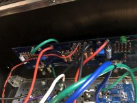
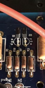
I see you have red as positive, black as ground, and green as negative.
I would prefer that you stick to the standard as red is always positive, black is negative, and green is ground.
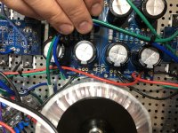
Also, if you look at the pic below. I prefer terminal blocks because if I make a mistake, and I make lots too, it makes troubleshooting easier.
Regards,
Dan

I see you have red as positive, black as ground, and green as negative.
I would prefer that you stick to the standard as red is always positive, black is negative, and green is ground.
Also, if you look at the pic below. I prefer terminal blocks because if I make a mistake, and I make lots too, it makes troubleshooting easier.
Regards,
Dan
Attachments
Thanks Dan. I am going to find some terminal blocks. The first build guide I was using did not use them. That is what led to a previous problem with my power supply.
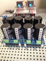
Found blocks on Digikey. I will make the recommended changes, as well as change the orientation of my capacitor board so that the connections are more easily accessible, as soon as I get the blocks.
Last edited:
Hey Dan, where did you find those terminal blocks?
Digikey or Mouser. I’ll post part numbers later today.
Regards,
Dan
Don’t worry about wire color. Just be consistent on both channels.
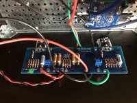
Your Jfets appear to be installed backwards. (and I think they are actually ZTXs...)
Your Jfets appear to be installed backwards. (and I think they are actually ZTXs...)
Attachments
Last edited:
I just saw this post. I was wondering about these suckers. I will fix them tomorrow and let you know how it works. I am still going to add the terminal blocks. Thanks
Well. There is no fixing them. There should NOT be ZTX devices in those positions. Q1, Q2 should be J-fets SJ(LSJ)74 and SK(LSK)170.
Okay. That is interesting. I wonder how I ended up with those there? Presbyopia? So I am back to tearing the boards out and finding new transistors. I really thought I had the dinghy ones in there. Bummer.
You need to buy 2 matched pairs from Diy audiostore. Or if anyone else have matched pairs. But do NOT buy chineese E-bay parts. The are most likley fakes.
I bought a set just now. That is where I got my first set. I have ztx devices in the 2 appropriate places on my boards.
I also have another question. The blue trim pots that came with my F5 parts kit do not seem to have a stop point when turned counter clockwise. Is that normal or should I replace them as well?
I also have another question. The blue trim pots that came with my F5 parts kit do not seem to have a stop point when turned counter clockwise. Is that normal or should I replace them as well?
That's normal for the trimmers. When you hear a click, it means the pot is at the end of its range.
- Home
- Amplifiers
- Pass Labs
- Another problem with my F5 build.