IRFP260 is a very powerful and robust device, good to learn with if you got them cheap 🙂 But they have high input capacitance which can make driving them difficult.
How much did you get them for?
How much did you get them for?
I bought them in pack of 25 pcs, totally 150 and the totally price of ~1$ each. I saw Swedish Elfa.se price was much more for one that I payed for 25...... Don´t ask me how but they went away cheap on the auctions..
Bengt
Bengt
It is Tradera.se, a swedish page for company and private sellers. Thoose was from a private seller and he had several moore that I did not get. And yes, the price sounds like a joke..... I don't know if he has more that he will sell.
Bengt
Bengt
Are they genuine IR parts? I just tried to search on www.tradera.com but no items matching were found.
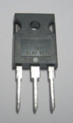
They look real, and are the original version not N suffix, which means they are better for linear use.
Seeing as you have so many, would you be interested in selling some? 🙂
Seeing as you have so many, would you be interested in selling some? 🙂
Here is something I've been playing with - an attempt at a very simple near rail-to-rail output amp. Keep in mind I've just picked the schematic out of the simulator so the two pots it has are shown as fixed resistors, and also there is a 0.001 ohm resistor for idle current measurement which of course would not appear in the real thing...
Attachments
Member
Joined 2002
I can give you my layout if you want to.
I have to change some things because I did some changes but I have a layout, I made it to make a prototype in Winboard.
Please tell me your opinions about the pictures
I have to change some things because I did some changes but I have a layout, I made it to make a prototype in Winboard.
Please tell me your opinions about the pictures
Hi Bengt
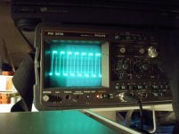
Yes the pics are helpful but could be better for interpretation.
On the 10KHz square wave i can see what looks to be x'over notch distortion about 1/3 way down the falling edge of the waveform. It's to be expected that this type of output stage is not so smooth. You will need to adjust the bias (and those 0.33 ohm resistors would be a help to have retained in circuit for setting ) to make sure you have a small but reasonable standing current , say 50mA. Next you should maximise global feedback to help smooth it.
You need to turn down the brightness on the oscilloscope so there's just a thin line without bloom. then change the timebase so only about 2-3 cycles occupy the whole screen.
Now, if you reduced the input stage current as I suggested you should have more OL gain and possibly some peaking on the square wave. This is good (for next step).
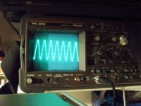
Your sine wave also needs toi be spread out more for only 2-3 cycles and reduce brightness. Is it 10KHz. Is the wave triangulating?
going well.
Yes the pics are helpful but could be better for interpretation.
On the 10KHz square wave i can see what looks to be x'over notch distortion about 1/3 way down the falling edge of the waveform. It's to be expected that this type of output stage is not so smooth. You will need to adjust the bias (and those 0.33 ohm resistors would be a help to have retained in circuit for setting ) to make sure you have a small but reasonable standing current , say 50mA. Next you should maximise global feedback to help smooth it.
You need to turn down the brightness on the oscilloscope so there's just a thin line without bloom. then change the timebase so only about 2-3 cycles occupy the whole screen.
Now, if you reduced the input stage current as I suggested you should have more OL gain and possibly some peaking on the square wave. This is good (for next step).
Your sine wave also needs toi be spread out more for only 2-3 cycles and reduce brightness. Is it 10KHz. Is the wave triangulating?
going well.
Amplifierguru, I'd love to read a comment on my simple design in post #28 if you have the time...
You put the aliens in the middle of this stuff and you got all the answers. Eat Static
Eat Static😀 😀 😀 😀 😀 😉 WOW , Ritchie you offered us to EAT STATIC , what if i offered it to Mr. MOSFET.😉
ilimzn said:Amplifierguru, I'd love to read a comment on my simple design in post #28 if you have the time...
The amp you degined is good as long as Rail loss is concerned, but if you relate it to sonic perspectisation, then its an over complex a little bit to do a favour in terms of good damping and sonicity.
Workhorse said:
The amp you degined is good as long as Rail loss is concerned, but if you relate it to sonic perspectisation, then its an over complex a little bit to do a favour in terms of good damping and sonicity.
Actually, it is intended to drive a subwoofer, and the damping factor for that use is more than adequate. Sound quality was surprisingly beter than expected when driven full range, and reminds a lot of a more powerful NAD3020.
Rail loss of course and simplicity were the prime factors - I would definitely not call it overcomplex. There are however a number of elements with not so obvious a use - the key is in the absence of any kind of regulated power supply as well as an auxiliary supply for the front end, and the high likelyhood of it being driven to clipping or current limiting. Because of this measures had to be taken to get relatively symetric and storage effect free clipping, as well as bias current stability over a wide variation of rail voltage (which boils down to a couple of diodes and resistors plus the use of a MOSFET in the VAS stage). One other thing: the IRF520 is the bias generator and should be on the output device heatsink.
posted reply on wrong thread, here it is -
Hi Ilimzn,
Sure I'll comment on your design. Firstly why pure Nch output? An exercise? The asymettry usually leads to high OL distortion and the symettrical complementary drive opportunity is lost.
Having said that, it appears to derive from the Bengt Ollsen design from EW&WW (Dec'94) "Better Audio from non-complements".
Why the 3K3 at input , you don't need it. Move the 560p to after the 1K - right to the input base. Bit more gain too (2.1dB). The 10K on TR1 emitter isn't really clean sourced (your sim won't show that up unless you put some hash on the 40V supplies) and the 18pF probably won't matter for a sub amp.
Does it really get to the +Vs rail?
Hard to believe.
- Status
- Not open for further replies.
- Home
- Amplifiers
- Solid State
- Another N-channel