Hi,
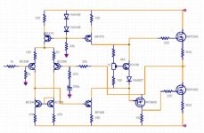
I am not soo good at this but very intrested and trying to learn about amps. I found a schema on a HEXFET amp, using IRF540 /9540 as O/P. I´m trying to make this as an n-channel amp, using some small ideas from Zeta (IRF9640 as an inverter). I have not simulated the construction but I have made a real, working prototype.
Well, sound is comming out but is seems to be difficult to set the bias correct. If I set the bias to 150mA it seems to decrease quick to a lower value of 50-70mA with the BD139 mounted on the heatsink of O/P. If i take it away from the heatsink the same happens but slower. I think this circuit is not good optimised.
It works but with all knowledge here maybe someone can give me some advise to make the circuit more stable and correct!
Regards,
Bengt

Bengt: This one will work fine. However your BIAS circuit is over compensated, you don't need a pure VBE multiplier.
Also you don't need the 0R33 Source resistors. Just leave them out, and connect the source directly.
Also you don't need the 0R33 Source resistors. Just leave them out, and connect the source directly.
Thanks for your reply mr Clausen
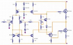
So I take away the BD139. I am not so familiar with n-channel but as the original O/P was IRF540/9540 and it was impossible to bias the circuit without BD139 VBE. In this one I am using IRFP260 and the whole circuit seems to behaive "different".
So, I will continue and play music from my ZAP Player.....
I can not have a better source I guess....
regards,
Bengt
No no don't take the BD139 away, reduce the vbe multiplication factor.
But take away the 0R33 resistors.
But take away the 0R33 resistors.
Thanks for your answer Mr Clausen
Ok, I took away the 0R33.
I missunderstood you, I think that only in amps with lateral mosfet you don't need "BD139" on the heatsink to prevent thermal runnaway as they have negative tempkofecient (?!). In this circuit BD139 will also compensate for heat and reduse the current to prevent thermal runnaway, did I understand this correct???
I will decrease 2k2 to 1k and increase 100 to 470ohm if I understood correct. BD 139 is needed for thermal compensation, right ?
Learning all the time....
Is it a good choise to use IRFP260 ? I have some of this transistors...
Regards,
Bengt
corrections
Yes, you are right, Drain and Source have to change in the schematic, on my testboard it is in the right place, else it would be fireworks perhaps....
I will change it.
Bengt
Yes, you are right, Drain and Source have to change in the schematic, on my testboard it is in the right place, else it would be fireworks perhaps....
I will change it.
Bengt
You might like to try adding a 100 ohm resistor in the source of the IRF9640. This may bring you a little better stability.
Thanks for your advise. Anyway I changed resistors around BD139, 2k2 to 10k and 100ohm to 2k9 and trimmer to 4k7. I also changed the base connection of BD139. It got little more stable. I will run the amplifier for some hours to check.
I will try to add a 100ohm resistor to IRF9640 tomorrow.
Bengt
I will try to add a 100ohm resistor to IRF9640 tomorrow.
Bengt
Attachments
Member
Joined 2002
hello Bengt
Good work - but could do with some improvement.
5mA input diff'l pair current could go down to 1mA or lower for a big reduction in input bias /offsets. try a 1K in the CCS
Keep the 0R33's and , if you have an oscilloscope, check the 10KHz sq wave, as the lower current input now has less degeneration and MORE LOOP GAIN for lower THD - partic to tame that output stage which is unlikely to be the picture of linearity. You may need some feedback lead comp.
You should have an RC to ground on the output 10ohm and 100nF say.
Good work so far. I was going to suggest that you change the pot connection to like that as it's safer in the even of a pot wiper failiure.
Hi Bengt,
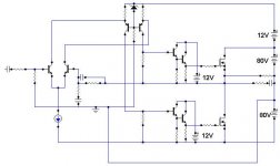
Your circuit is very good & nice, but it suffers from rail loss of about 4 to 5 volts due to the high Vgs of mosfets. This type of circuit works best with Bipolars but with mosfets it is very inefficient.
The output voltage swing cannot reach upto supply rails.
All the Great members here knew this, but i donot know why they have not said this point. maybe something.......🙂
regards,
kanwar
It's a valid point, but the amp is quite simple and for a first attempt it's more about learning than making the best/most efficient 🙂
Thank you for all support.
I added a R/C at the output already but did not in the schematic. I have an old philips oscilloscope and a tone generator and I will do tests as amplifierguru suppose later this day and try to post some photos.
Yes, this is a simple construction and inefficient. The rail is +-66v 500va unreg and I use 2x 22000uf. The reason I use only IRFP260 is that I bought lots of them at tradera.se . I was looking to build Zeta but wanted to try if I could remake an other construction.
I´ll send pictures later,
Regards, Bengt
- Status
- Not open for further replies.
- Home
- Amplifiers
- Solid State
- Another N-channel