Hey Anyone,
When I rebuilt my Dynaco Mark VI's I added A CL60 NTC thyristor in place of the time delay relay tube. I placed it at the output from the power supply. In looking at the original schematic today I noticed that the original took the B+ for the output transformer from between the choke and the second filter cap. It seems to me that having the delay for the output tubes would be a good thing. I may be wrong on this. Attached is the original schematic. The red line is where my transformers draw power. Does it make a difference?
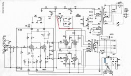
When I rebuilt my Dynaco Mark VI's I added A CL60 NTC thyristor in place of the time delay relay tube. I placed it at the output from the power supply. In looking at the original schematic today I noticed that the original took the B+ for the output transformer from between the choke and the second filter cap. It seems to me that having the delay for the output tubes would be a good thing. I may be wrong on this. Attached is the original schematic. The red line is where my transformers draw power. Does it make a difference?
Attachments
I personally don't like the bias circuitry on that amp.
If the wiper of the bias pot ever loses grip, it'll cause the bias to drop and destroy/redplate the outputs if you're not nearby, like in another room at the time.
A high value resistor (experiment) from the wiper to the pot on the side of R104 would save the tubes.
If the wiper of the bias pot ever loses grip, it'll cause the bias to drop and destroy/redplate the outputs if you're not nearby, like in another room at the time.
A high value resistor (experiment) from the wiper to the pot on the side of R104 would save the tubes.
There's no problem hot-starting 6550s at Dyna's voltages.
IMHO the delay-relay mutes the turn-on thump. Bypass it, wrap it carefully, and sell it on ePay-- they get good money now.
I never noticed, but the Bohemian has a good point about bias-pot failure.
IMHO the delay-relay mutes the turn-on thump. Bypass it, wrap it carefully, and sell it on ePay-- they get good money now.
I never noticed, but the Bohemian has a good point about bias-pot failure.
The time delay tube make little sens AT ALL here providing that :Hey Anyone,
When I rebuilt my Dynaco Mark VI's I added A CL60 NTC thyristor in place of the time delay relay tube. I placed it at the output from the power supply. In looking at the original schematic today I noticed that the original took the B+ for the output transformer from between the choke and the second filter cap. It seems to me that having the delay for the output tubes would be a good thing. I may be wrong on this. Attached is the original schematic. The red line is where my transformers draw power. Does it make a difference?
1/ the cap C102 has 500V limit
2/ a diode 1n4148 is mounted between pin 9 ( grid) and pin 9 (cathode) of 7199. This prevents the grid to have more then 0.5V more positive then the cathode, when tube is operating the diode is blocked and does no harm.
Switching powertubes might even harm them as a big "thump" will occur instead if a soft increase of current as cathodes warms up.
There's no problem hot-starting 6550s at Dyna's voltages.
.
The MkVI uses 8417.
Are you still using them?
One of the biggest weaknesses of that dynaco design is attempting to run it ultra linear connection with the wrong drive and A-A impedances.
It doesn't work.
I have seen 8417 break out into the most anode melting devastating oscillation and self bias when driven badly.
Because of the pecularities of that valve with its non aligned grids, (ie. extremely high screen grid currents), attempting to do what Dynaco did, results in high distortion, generally poor sound & extreme unreliability.
Quicksilver did exactly the same & failed.
Fisher and Bogen basically got it right, because those valves were specifically designed by Westinghouse for Fisher.
Fisher drove them with an extremely good driver stage, and throttled them back to 60W.
Bogen ran most of them close to class B with weak PSUs,ie,- not exceeding 60W, with A-A 6k5, so they just last & last.
They did push them to 120W using a quad, plus much lower A-A load (3k3), again with a small PSU & class B. (non hifi original useage).
It's far better and more sensible than Dynaco did, and they simply don't blow up.
The amps now run 6CG7 front end with a 6CG7 LTP. Outputs are KT88's with fixed bias. I guess my real question has to do with inrush current. Before I put the CL 60 in it would blow the main fuse instantly. I'm also running more capacity in the PSU caps as well. Since the time delay tube only supplied the front end in the original it was probably for turn on thump. In my case it is there limit the inrush current. As it is the PSU charges the caps first. Then as the cathodes heat up and start to draw current the thyristor opens up slowly to allow current to flow through the tubes.
If you run away from KT88, fitted xAV5/xFW5 with screen drive you would get masses more power and not worry about UL.
It would probably make a really good sounding amp at last with no more blown fuses or worries about blowing up.
remember this? The Sylvania 6AV5 doing 42W Pa?
What's not to like?
half an amp cathode current at 80V?
It would probably make a really good sounding amp at last with no more blown fuses or worries about blowing up.
remember this? The Sylvania 6AV5 doing 42W Pa?
What's not to like?
half an amp cathode current at 80V?
- Home
- Amplifiers
- Tubes / Valves
- Another Mark VI Question