Hi Choky!
Maybe a silly question (but pls no silly answer!) or maybe already asked you too many times, but where can we buy the pcbs as seen in post 32?
I'm mainly interested on a couple of the shunt reg pcb.
Maybe a silly question (but pls no silly answer!) or maybe already asked you too many times, but where can we buy the pcbs as seen in post 32?
I'm mainly interested on a couple of the shunt reg pcb.
massimo said:Hi Choky!
Maybe a silly question (but pls no silly answer!) or maybe already asked you too many times, but where can we buy the pcbs as seen in post 32?
I'm mainly interested on a couple of the shunt reg pcb.
well - I'm not responsible for pcbs ( I am just for back of napkin sketch of circ
 ) , but you can ask bogdan_borko for that ;
dunno - seems that zei is working on split version ( Shinyy , in my hysteric nomenclature
 ) ; you can look in digital , Papa's D1 pcbs thread .....
GuidoR said:Hi all,
In case somebody agrees, here's the artwork of the Shinyy 🙂att'n: not yet tested!!!).
Guido
Massimo, in the next days I'll etch my sample: do you need one, too?
e-mail me 🙂
Guido
GuidoR said:The files (Express PCB)
😉
btw - express pcb file is Isnogood 😉 for any other proggie
GuidoR said:Hi all,
In case somebody agrees, here's the artwork of the Shinyy 🙂att'n: not yet tested!!!).
Guido
Massimo, in the next days I'll etch my sample: do you need one, too?
e-mail me 🙂
Guido
Thank you for your offer, Guido.
No, I need a dual mono p.s. (2 x Shiny), not a dual p.s. (Shinyy).
I'm now working on my own pcb.
Alors,
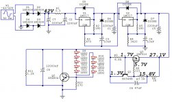
I built a shunty for the B1 but it won't turn on.
I hooked the circuit up to 42VDC and it draws like 60mA.
The section with the LM317s seems fine and puts out 27V.
But the voltage at the gate of the IRF510 won't rise above 5.7V. I replaced the FET. The one pulled from the circuit looks fine so it's likely that this wasn't the problem.
Could the BC546B be the cause?
(the darlington in the sim is not the actual one, it's a BDX53C)
The second channel I build won't turn on either, so I must have made the same mistake twice, hopefully.
Maybe someone can give me a hint.
Thanks guys!
Attachments

Alors,
I built a shunty for the B1 but it won't turn on.
I hooked the circuit up to 42VDC and it draws like 60mA.
The section with the LM317s seems fine and puts out 27V.
But the voltage at the gate of the IRF510 won't rise above 5.7V. I replaced the FET. The one pulled from the circuit looks fine so it's likely that this wasn't the problem.
Could the BC546B be the cause?
(the darlington in the sim is not the actual one, it's a BDX53C)
The second channel I build won't turn on either, so I must have made the same mistake twice, hopefully.
Maybe someone can give me a hint.
Thanks guys!
circuit can't draw more than 0V65/R9
disconnect everything after CCS , then connect output of CCS via mA-meter to gnd and check current ;
on schematic everything looks good to me ; culprit must be somewhere in your actual implementation ;
did you checked twice orientation of parts , especially BDX ?
it's
Attachments
Last edited:
Thanks a lot, choky, I think I'm on to something. I disconnected everything after the CSS and checked what current it would push through a DMM to ground. It's around 50mA, just as expected. Unloaded it puts out some 25V, haven't checked the voltage with a load, but will do tomorrow.
So the error must be in the shunt-regulator part. I'll check all polarities and keep you posted. Hope I see them LEDs actually emit someday.
Thanks a lot!
So the error must be in the shunt-regulator part. I'll check all polarities and keep you posted. Hope I see them LEDs actually emit someday.
Thanks a lot!
For some reason I had the darlington wired incorrectly. Had the pinout right but messed up the wiring...
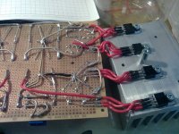
Well , now it's working. I'll post some circuit-pr0n tomorrow.
In the meantime I have a question: After some mods one shiney puts out 18V@80mA and the other puts out 28V@110mA, so both behave nicely. The circuits are fed from a DC-psu at the moment. I'll get a toroid with twin 18VAC secondaries (36VAC in series then, and hopefully some 50V rectified). The choice is between a 40VA "Block" toroid and a 120VA "Multicomp" toroid. Price is the same.
Both have dual primaries, which is nice for a cl-60 type softstart. Neither of them has an electrostatic screen, so no winning argument here. The "Block" seems to be manufactured in Germany, the Multicomp I don't know. The smaller one probably offers more regulation but in turn might take less abuse. 40VA surely is enough for the application but it seems so weak...so which one would you guys buy?
- Status
- Not open for further replies.
- Home
- Amplifiers
- Pass Labs
- another local NS10 & Shiny