H
HAYK
The error amplifier amplifies and integrates in open loop mode only the error between the output and the input. As the output of the power amp is reduced back to unity gain, the power amp doesn't influence the performance of the error amplifier hence it doesn't diminish the drawbacks of the error amp as required to be qualified as composite. It is the same for an added servo.Where did they write "gets influenced"?
You have two opamps, one amp with high power/voltage but low precision and one small-signal amp with high precision but low power/voltage. The composite yields a power amp with high precision, exactly combining the benefits of each, power from the first and precision from the second.
You are repeating the commercial statement of Neochrome that a low precision amp is controled by a high precision one, what is a high precision amp according to you?
Discussion with you about semantics is futile it seems, so let's agree to disagree ;-)
OK, one last time, couldn't resist: The error amp can't deliver neither much current nor voltage, which is its drawback. A composite can and will have the precision specs (offset, noise, gain) of the small amp... and when done right, even much better distortion specs than the small-signal amp alone, at audio frequencies.
OK, one last time, couldn't resist: The error amp can't deliver neither much current nor voltage, which is its drawback. A composite can and will have the precision specs (offset, noise, gain) of the small amp... and when done right, even much better distortion specs than the small-signal amp alone, at audio frequencies.

You're making a lot of assumptions with that statement. The supply hum in ASR's measurements comes from the fact that the power supply sits atop the amplifier channels and radiates into the amp input cabling. It has nothing to do with PSRR. There's very little I can do about that aside from making the chassis larger.Despite error corrector, the Power supply rejection ratio is very bad.
My challenge with the Modulus-286 Kit LE was to shoehorn it into one of the smaller MiniDissipante chassis. The thing is tiny.
No I don't. That's obvious in the THD+N graphs that are on the Modulus-286 product page. I've added them below so you don't have to hunt for them.On the other hand you are giving the same THD+N for 8 ohms and 4 ohms at 10mw
Note that these were measured with the APx525, not the 555. So the THD+N shown here is mostly limited by the test equipment.
Also see Toppings issues with exploding amps: https://www.audiosciencereview.com/...off-but-connected-to-power-still-works.38979/See also topping LA90 with 3886.
There's more to amplifier performance than good measurements. Sadly, that part is missed by most of the ASR crowd these days. All they seem to care about now is dB SINAD per dollar. But that's their choice.
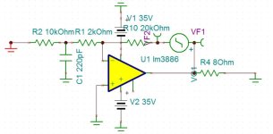
Would you elaborate on that? I'm not sharing the schematic of the Modulus-86, so I'm curious what you're referring to there.The circuit shown is not mine it is given with Modulus-86 board. I'll give you the source on your private mail because of copyright.
That's respectable.My amplifier clears -100dB 0.001% THD+N 1khz and I am happy with that. Second harmonic is dominant wich is an extra bonus. 10khz is around -86dB 0.005% THD+N but is usually like that.
Tom
H
HAYK
Precision opamps.Discussion with you about semantics is futile it seems, so let's agree to disagree ;-)
OK, one last time, couldn't resist: The error amp can't deliver neither much current nor voltage, which is its drawback. A composite can and will have the precision specs (offset, noise, gain) of the small amp... and when done right, even much better distortion specs than the small-signal amp alone, at audio frequencies.
https://www.digikey.com/en/articles/how-to-choose-and-use-precision-op-amps-effectively
H
HAYK
The DS shows 0.03% THD+N for 10mw 1 kHz 8 ohm. The graph above shows more than 0.01% for Modulus 286, this is only 3 times enhanced.

The THD+N at 10 mW is dominated by the +N. That's set (mostly) by thermal noise from the resistors in the circuit, so it's no surprise that the composite architecture helps little there. Fun begins when you look at THD+N vs output power and, especially, THD+N vs frequency.
Also, 3x improvement is 10 dB. That's nothing to sneeze at.
As I've been saying over and over: You have to look at more than one measurement.
Tom
Also, 3x improvement is 10 dB. That's nothing to sneeze at.
As I've been saying over and over: You have to look at more than one measurement.
Tom
H
HAYK


H
HAYK
If both 4 and 8 ohms have the same N% With 1.414 times more level, the measurement is corrupt.
The 3886 alone has 0.025% THD+N with full harmonics. With Modulus-86 it gets 0.004% with only 2 harmonics (filter 60khz) concidered, this gives an enhancement of less than 6 times probably between 4-5 times.
By reducing simply the audio band gain and amplifying with a low THD+N opamp one can get easily better result, what the OP will be doing.
H
HAYK

H
HAYK
H
HAYK
I got confused with the noise level of 3886 alone with 20k/1k.
10-20khz it is 6mv, with circuits above it is 0.75mv. This is 8 times less noise, THD.

10-20khz it is 6mv, with circuits above it is 0.75mv. This is 8 times less noise, THD.
I think there's an error in that plot. I need to retake those data.They are equal at 10mw.
Tom
HAYK, I can see how your circuit would reduce the LF gain of the 3886 while maintaining the HF gain high, but your Bode plot doesn't look right. Could you repost in larger size please? I tried to compute the gain (not in a simulator, just by hand) and would like to compare to your plot.
H
HAYK
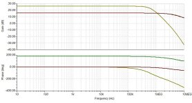
Surely both R2 and R3 should be the same, i.e. both 10 k or both 12 k?
The noise gain of the 3886 is kept at 11. This maintains stability, but it also means that the loop gain available for distortion reduction is the same as if the 3886 were configured to have a total gain of 11. So this is not going to reduce distortion.
What it will do is reduce noise because the input signal to the 3886 is larger.
H
HAYK
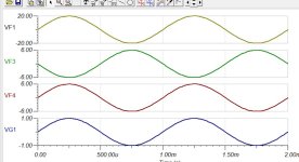
If the input is differential only then R2=R3. If single ended, the inverter gain is R3/2k and the non inverter gain is (R2+2k)/2k. This why to pour symmetrical outputs with each, a gain of 6. See VF3 and VF4 graphs.
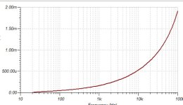
The Amp at low frequencies has 12db higher NFB than with 20k/2k alone.
See the graph bellow.


The Amp at low frequencies has 12db higher NFB than with 20k/2k alone.
See the graph bellow.
Attachments
- Home
- Amplifiers
- Chip Amps
- Another LM3886 in parallel attempt - this time 4 of them!