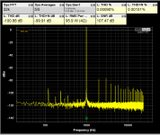
4R load results are good but not as good as 8R.
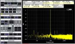
Even though THD+N is way better that of the datasheet, I am still far from achieving the level of performance of the Modulus line of amplifiers.
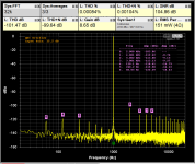
Note how 2nd harmonics is dominant in all of the measurements.
Looks like VAS stage is running out of juice (distorting) earlier then output devices.
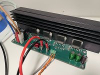
By using four LM3886s output stage is equivalent to four pairs of output transistors or 2EF-4.
Even though THD+N is way better that of the datasheet, I am still far from achieving the level of performance of the Modulus line of amplifiers.
Note how 2nd harmonics is dominant in all of the measurements.
Looks like VAS stage is running out of juice (distorting) earlier then output devices.
By using four LM3886s output stage is equivalent to four pairs of output transistors or 2EF-4.
Attachments
Seems reasonable.4R load results are good but not as good as 8R.
That would not surprise me. The VAS probably runs out of headroom before the CCS that feeds it. The output devices are probably limited by how much power can be dissipated in them safely.Looks like VAS stage is running out of juice (distorting) earlier then output devices.
Tom

H
HAYK
Amazing decrease of noise, what as the culprit?
In real it should be even less as you are only 7db to the limit of your measuring equipment given THD+N -110db.
On post 40 5w 1khz and post 41 are not same, what happened.
You have a Modulus-86, measure it with your equipment to be in relative.
With 90w the THD and THD+N should be very near, it is not the case as if your measuring equipment is injecting the noise.
Last edited by a moderator:
Hi KSTR & Tom,
Thanks for taking time for detailed answer, nice reading with morning coffee 👌.
On DC offset, fully agree, but I put an capacitor between R2 and R4 (Ref picture in #37)?? I know it would not work without it.... Did you see it in center of my drawing?
On stability, my present amps work with one nfb capacitor per chip and than to the ground, that's stable. Only balanced signal is used, didn't try unbalanced.
@tomchr, except golden reservoirs caps, there are Murata 10microF smt ceramics per leg per chip, so 12 pc per chanel. They are very small so might be you didn't spot them on the picture.
This is real life when components are ok.I measured Voffset at the output pin of each IC and I got -1.8mV -1.7mV 0.8mV and 1.1mV
for one channel for now.
Total 2.9 mV DC offset device by 0.2 ohm is 14.5 mA of wasted DC current, not much to worry
Your single capacitor between the legs of the bridge does reduce DC gain of the whole bridge to unity, but not the differential DC gain the opamps see inside the bridge legs.On DC offset, fully agree, but I put an capacitor between R2 and R4 (Ref picture in #37)?? I know it would not work without it.... Did you see it in center of my drawing?
You people made me do it, I gutted Amp module out of one of my speakers. It was not my plan but now I'm going to powered them up on a bench and measure different feedback arrangements.
Let's see what comes up, if I'm wrong that's super ok, let's do it
A question @pbilous, is it OK with you that I post 5 - 6 posts on this here in your thread, as progress is happening? It's your thread after all, I respect.
And 2 times mea culpa:
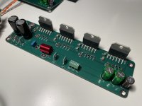
1. Load sharing resistors in my original are not 0.1 but 0R22 1% , sorry, I assamble this in 2005, that was long ago
2. PCB s are not really professional and have many mistakes, see pictures below. But they are as they are, hope it will not affect measurements to be useless, let's see...


Let's see what comes up, if I'm wrong that's super ok, let's do it
A question @pbilous, is it OK with you that I post 5 - 6 posts on this here in your thread, as progress is happening? It's your thread after all, I respect.
And 2 times mea culpa:
1. Load sharing resistors in my original are not 0.1 but 0R22 1% , sorry, I assamble this in 2005, that was long ago
2. PCB s are not really professional and have many mistakes, see pictures below. But they are as they are, hope it will not affect measurements to be useless, let's see...
QA401 attenuation settings - reduced to 18dbvAmazing decrease of noise, what as the culprit?
agreeIn real it should be even less as you are only 7db to the limit of your measuring equipment given THD+N -110db.
8R vs 4ROn post 40 5w 1khz and post 41 are not same, what happened.
good idea thanks!You have a Modulus-86, measure it with your equipment to be in relative.
I tried using the lowest attenuation possible but had to stop at 24 as lowering it overloaded ADC.With 90w the THD and THD+N should be very near, it is not the case as if your measuring equipment is injecting the noise.
Cheers pbilious,@Drbulj
It would be nice if you started own thread, just post link here so we can follow. I’m curious about your project for sure man
You can learn JLCpcb editor - super easy to make your own PCB, lke $6 for 5 shipping included
Okidoki, I'll open another thread.
Today I use kicad, that's fine. But then when this was made I had only Autocad, that's not exactly best for this purpose... But then I'm mechanical engineer, not electrical 🤓
Talk to you soon
The output devices are probably limited by how much power can be dissipated in them safely.
That is why I went for the non-insulated package LM3886T - I want to maximize heat transfer and thus lower the stress for output transistors.
H
HAYK
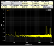
The noise you are getting measured is wrong. With 5w 8ohm it says SNR 107db with 50w 8ohm it should measure 117db but it doesn't, it says 107db. By this, one can conclude that the noise remained constant although you attenuated by 10db and it is the noise of the ADC. To get right measurements, first see the noise measured without any input. Then apply the amp, with no signal and measured noise without any attenuation and subtract from the precedent to know exactly in uV your amp noise. Then you make the proportion SNR calculation by hand to add to that of THD to get the real THD+N.
True, in practice you will most often see offset values which are way below the max rating from the datasheet but conservative design means you cannot rely on that and a circuit should behave well even with worst-case assumptions. For DIY builds, no problem, just measure and confirm stuff is within reasonable bounds but for robust industrial designs in mass production you'd better be safe than sorry.Hi KSTR, I got you now, thanks for explaining. Nevertheless I still have experience, as @pbilous measured, DC offset of these chips is very small and will provide no harm.
Still trying to get the hang of the audio interface.
Below are attached loopback measurements. It looks like noise floor for the generator is 110dB. Noise floor for the ADC is better at around 117dB.
If I set my generator to +6dBV and my ADC to attenuate to 6dBV I can get better SNR.
Below are attached loopback measurements. It looks like noise floor for the generator is 110dB. Noise floor for the ADC is better at around 117dB.
If I set my generator to +6dBV and my ADC to attenuate to 6dBV I can get better SNR.
Attachments
H
HAYK
At 0dbv your are at maximum, above, the ADC is saturated. For that bring your fundamental at -6db to give half of the definition to measure the noise and harmonics.
Your software does measure the RMS value of total signal, find a way to limit it to 80khz, by sampling rate for example, as is measured on the DS. It is very important that first you get a precise value of the noise. Your 8bit scope can also measure the noise of the amp with no signal to counter check the result. Once you have the rms value, you just get the ratio in % with the fundamental rms value to add to the THD manually.
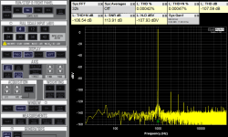
Bellow is the Modulus-86 THD+N, at 10mw 8ohm, which is mainly N, it is 5 times only lower than DS.
PS. I forgot about the generator noise 110db which is going to be amplified that also needs to be subtracted.
Your software does measure the RMS value of total signal, find a way to limit it to 80khz, by sampling rate for example, as is measured on the DS. It is very important that first you get a precise value of the noise. Your 8bit scope can also measure the noise of the amp with no signal to counter check the result. Once you have the rms value, you just get the ratio in % with the fundamental rms value to add to the THD manually.
Bellow is the Modulus-86 THD+N, at 10mw 8ohm, which is mainly N, it is 5 times only lower than DS.
PS. I forgot about the generator noise 110db which is going to be amplified that also needs to be subtracted.
Attachments

Last edited by a moderator:
I will never understand why people are still so fixated on THD+N in a combined measurement. THD+N comes form the old days when THD was always sufficiently larger than N and measurement systems were limited to looking at the RMS output level of a notch filter. Spectrum analysis was way out of reach, back then.Even though THD+N is way better that of the datasheet, I am still far from achieving the level of performance of the Modulus line of amplifiers.
Much better is to look at sets of THD spectra, stepped in level and frequency, and look at the noise separately. That tells you what's really going on.
In my experience there's actually little practical difference between the LM3886T + thermal pad and the LM3886TF. You need to be running heat sink temperatures in excess of 100 ºC to see any difference as I recall. I posted some data here: https://www.diyaudio.com/community/threads/lm3886-thermal-experiment-with-data.265771/post-4144753That is why I went for the non-insulated package LM3886T - I want to maximize heat transfer and thus lower the stress for output transistors.
Tom
I am still amazed at the low distortion you achieved, e.g. -110 dB harmonics for 5 W / 8R / 1 kHz, and most recently -105 for 4R. That is nearly composite amp territory whereas the -90 dB you had before that for 5 W / 4 R is more what I would expect for a 3886 with carefully balanced impedances but no additional loop gain.
Yeah, LM3886 is amazing chip amp IC!
By paralleling four ICs I was able to minimize lagre signal nonlinearity caused by output transistors pumping too much current.
In other words by splitting current between four ICs I was able to eliminate the biggest contributor of the distortion.
In fact, now it is a VAS that is a limitation. You can see it by the harmonic spectrum of the FFT - look at the second harmonic - it is the largest at -103 dB (4R 5W graph).
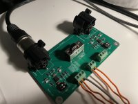
I have decided to split design into two PCBs - one is the input buffer for balanced signal, and the second is the power board with four LM3886s. Input buffer has three settings for gain and 2CH to BTL mode switch.
By paralleling four ICs I was able to minimize lagre signal nonlinearity caused by output transistors pumping too much current.
In other words by splitting current between four ICs I was able to eliminate the biggest contributor of the distortion.
In fact, now it is a VAS that is a limitation. You can see it by the harmonic spectrum of the FFT - look at the second harmonic - it is the largest at -103 dB (4R 5W graph).
I have decided to split design into two PCBs - one is the input buffer for balanced signal, and the second is the power board with four LM3886s. Input buffer has three settings for gain and 2CH to BTL mode switch.
Attachments
- Home
- Amplifiers
- Chip Amps
- Another LM3886 in parallel attempt - this time 4 of them!