Hi Fred,
Your DVM reads as the display shows, you don't have to calculate anything. The test current is normally around 1 mA. The Heathkit has two ranges as you've pointed out. Very high voltage transistors and RF transistors tend to have lower gain than the transistors you will run into in audio. Older JAN (North American) outputs often have low beta as well. There will be a lot of variance in beta readings for JAN parts to be expected.
Leakage in a silicon transistor is simply not allowed. In fact, if you read leakage while testing a silicon transistor, check you aren't touching any part of the transistor. If you aren't, try cleaning the transistor and test it (them) again after they have dried. Germanium transistors do have a great deal more leakage current than silicon parts. You should be able to find the limits on a data sheet. Leakage always increases with temperature. If you suspect a transistor is intermittent, measure beta as you warm up the suspect transistor, also checking the leakage from time to time. I have had the leakage suddenly increase, and other transistors have dropped their beta to zero as they warm up. Again, suddenly with no warning. This meter is very useful if you think outside the box a bit. One warning. Make sure you do not melt your IT-18 with a hot air gun or anything else.
The scales on the IT-18 are X1 and X10. Read the scale directly on the X1 scale and multiply the meter indication by a factor of 10 on the X10 scale. I normally start on the X10 scale because most transistors have beta higher than 20. So, set the beta cal so the pointer sits over the furthest right hand lines on the meter scales. Don't touch that again for the short time you are using it at one sitting. These meters do not have the best balance, so set the cal with the meter level and do all your testing in the same position. Also, try to keep the transistor you are testing at room temperature. Don't hold it in your hand or fingers. Try this with a signal transistor and note the changes in your reading.
Just a a side note, I replaced the clips on the test lead to the "mini-grabber" style. It holds onto leads better, but it's a pain in the drain for TO-66 and TO-3 devices. In that case, clip onto an "alligator lead" and use that to hold onto the case.
-Chris
Gee, I can never keep these models straight until I have one in front of me on the bench. You are correct, there are no heat sinks on this model. If you did add a small heat sink to these, you have to support their weight in some way. It's possible RTV sealant (silicon) might work. You can't use a lot as you would only block some of the air flow. Maybe some around the leads to the transistor?In my amp, these were not mounted to any heat-sinks (see the pic at post #73). Perhaps another tech removed them and forgot?
No, you shouldn't have any problems unless the beta is well out of range for these devices. I just take every opportunity to improve things when working on anything. I don't go crazy, but the small touches can improve the sound quality.I did not match the devices' beta. Is that going to be an issue (at least for the purposes of the repair)?
With the resistor as in the manual?I double-checked the calibration and it is correct.
Okay, that's great! It never pays to have any doubts on your test instrument readings. It is not foolish to test the battery, that's step #1 in calibration. We actually threw out the batteries and installed new alkaline batteries. Can you measure the battery voltage inside the case where the battery clips solder on? That will ensure that there is full continuity right into the circuit. Something doesn't look right with your beta measurements.I cleaned all the contacts and switches with Deoxit contact cleaner. The battery reads a healthy 1.5v.
Your DVM reads as the display shows, you don't have to calculate anything. The test current is normally around 1 mA. The Heathkit has two ranges as you've pointed out. Very high voltage transistors and RF transistors tend to have lower gain than the transistors you will run into in audio. Older JAN (North American) outputs often have low beta as well. There will be a lot of variance in beta readings for JAN parts to be expected.
Leakage in a silicon transistor is simply not allowed. In fact, if you read leakage while testing a silicon transistor, check you aren't touching any part of the transistor. If you aren't, try cleaning the transistor and test it (them) again after they have dried. Germanium transistors do have a great deal more leakage current than silicon parts. You should be able to find the limits on a data sheet. Leakage always increases with temperature. If you suspect a transistor is intermittent, measure beta as you warm up the suspect transistor, also checking the leakage from time to time. I have had the leakage suddenly increase, and other transistors have dropped their beta to zero as they warm up. Again, suddenly with no warning. This meter is very useful if you think outside the box a bit. One warning. Make sure you do not melt your IT-18 with a hot air gun or anything else.
The scales on the IT-18 are X1 and X10. Read the scale directly on the X1 scale and multiply the meter indication by a factor of 10 on the X10 scale. I normally start on the X10 scale because most transistors have beta higher than 20. So, set the beta cal so the pointer sits over the furthest right hand lines on the meter scales. Don't touch that again for the short time you are using it at one sitting. These meters do not have the best balance, so set the cal with the meter level and do all your testing in the same position. Also, try to keep the transistor you are testing at room temperature. Don't hold it in your hand or fingers. Try this with a signal transistor and note the changes in your reading.
Just a a side note, I replaced the clips on the test lead to the "mini-grabber" style. It holds onto leads better, but it's a pain in the drain for TO-66 and TO-3 devices. In that case, clip onto an "alligator lead" and use that to hold onto the case.
-Chris
Hi Fred,
-Chris
Well, notice that many members jumped in trying to help you out here. Thank the forum, the forum is everyone here.Thanks for your faith and optimism! And mainly, thanks for all the help.
MCM is advertising some, but better make sure they are not "substitutes". They do have 27 of 2SC2912 on hand as the proper number at $1.35 ea. They list 83 of 2SA1210 at $0.83 ea. This is looking at Newark's site, so you should be okay there. Let's worry about substitutes when the time comes.In case I can't find suitable 2SA1210's and 2SC2912s, what would be a good substitute?
-Chris
More test results
Pulled and test the Q7 and Q4 (from MCM) replacements that were installed to replace the original parts. (These were installed when the amp was overheating R22).
Q7
beta: 90 (via DVM)
Q4
beta: 269 (via DVM)
The IT-18 did not indicate any leakage, but I'm not highly confident in the instrument.
Clearly, these are nowhere near matching and Q7 has borderline gain (should be min. 100). Are they close enough for general circuit operation? Should I reinstall them?
I have more coming from MCM, so I will try to find a better matched pair to install.
Last edited:
Hi Fred, all,
The discussion on the Heathkit IT-18 has been split and moved here.http://www.diyaudio.com/forums/equipment-tools/161012-heathkit-18-transistor-tester-troubles.html#post2079895
The discussion on the Heathkit IT-18 has been split and moved here.http://www.diyaudio.com/forums/equipment-tools/161012-heathkit-18-transistor-tester-troubles.html#post2079895
Hi Fred,
All right, you should probably replace both the 2SC2912 and the 2SA1210 as a pair. <snip> Do yourself a favor and buy 5 of each transistor so you can try to match the NPN with PNP beta.
Okay, I replaced Q4 (2912) and Q7 (1210) with tested new stock. No leakage. They were pretty closely matched at 258 and 222 hfe (according to my DVM's test).
I tested Q8 (which had been installed earlier) to double check it had no leakage. It had a gain of 415 hfe.
I tested R22 (which had smoked earlier) and it was correct at 5.1 ohm.
I re-soldered the board's ground connection to make sure it was good after all the wiggling.
I should get my Variac on Tuesday. And I now have a working oscilloscope. What would you guys do next?
cheers,
Fred
I would get a very bright light and a magnifying glass - bigger the better - and go over that PCB very carefully looking for bad solder. There is something strange going on that sound more like bad connections than bad parts.
G²
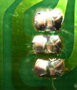
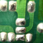
Okay G2, here are pix of the connections of the three transistors and 2 resistors I replaced. They look good to me. I did continuity tests to be sure there were no solder bridges. (There weren't.) In fact, if you look closely you can see the indentations from the test probes. Cool! What do you think? Any other tests or things I should do to check the assembly work?
Attachments

Last edited:
Hi Fred,
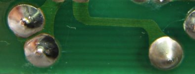
Your last picture on the right appears to be of a bad connection. Really bad.
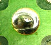
The previous pictures in post #107 all seem to have fibers around the connections. Try brushing with a clean toothbrush to get rid of them. Don't apply a high amount of pressure while cleaning.
Let's wait for the variac, then you can give the amp partial power. This allows you to take measurements before smoke come out.
-Chris
Your last picture on the right appears to be of a bad connection. Really bad.
The previous pictures in post #107 all seem to have fibers around the connections. Try brushing with a clean toothbrush to get rid of them. Don't apply a high amount of pressure while cleaning.
Let's wait for the variac, then you can give the amp partial power. This allows you to take measurements before smoke come out.
-Chris
Okay G2, here are pix of the connections of the three transistors and 2 resistors I replaced. They look good to me. I did continuity tests to be sure there were no solder bridges. (There weren't.) In fact, if you look closely you can see the indentations from the test probes. Cool! What do you think? Any other tests or things I should do to check the assembly work?
Well, your soldering skills are well above average. You're not afraid to get it hot enough - that's good. The camera works pretty well too. When you get the variac you can ramp up the power comparing the good channel to the bad and see where it fails. I would initially be watching to output DC and since you now have a scope, that would be a fine place to probe in DC coupling. If the scope is dual channel, one probe on each output would be an excellent way to start. Do you happen to have a Kill-A-Watt power meter? Don't bother to get one just for this but it would be a useful tool. I checked my 555 a few weeks back and it idles around 35 Watts with 122V power in. With your scope attached you'll be able to see if it breaks into oscillation.
Your solder joints look good. Is the rest of the board that good too? FWIW I was in our DLP TV last year changing caps and under close visual I saw what looked like a ring of dust around one lead. The 'dust' was a cracked joint and the component was an inductor in the primary AC in. Works a lot better with good connections. Under those conditions I do NOT reheat the existing solder. I remove it and use new solder and then clean off the flux.
Good Luck
G²
Hi G²,
-Chris
Yes, and don't forget to clean the component lead as well. They tend to oxidize, so pull the lead out the other side and clean it with something, even fine sandpaper. I find that liquid solder flux helps in these situations as well. Cleaning up after you're done is the only way to watch for bad connections and solder bridges. The connection should be very reliable after that treatment.Under those conditions I do NOT reheat the existing solder. I remove it and use new solder and then clean off the flux.
-Chris
Hi Fred,
Your last picture on the right appears to be of a bad connection. Really bad.
The previous pictures in post #107 all seem to have fibers around the connections. Try brushing with a clean toothbrush to get rid of them. Don't apply a high amount of pressure while cleaning.
I think you're seeing a trick a light on that last connection (that's the ground wire). But I reflowed it anyway and checked continuity from the PCB's pad to the grounding bar where the wire connects. It's good, even if I wiggle the wire.
I cleaned some more with a cleaning brush. I think some of the "fibers" you're seeing are light scratches in the surface of the board (although there was one dog hair. Everything I own has dog hair on it!)
I thought it was best not to use a toothbrush because the nylon bristles can create static. Is that an old wives' (tech's) tale?
When you get the variac you can ramp up the power comparing the good channel to the bad and see where it fails. I would initially be watching to output DC and since you now have a scope, that would be a fine place to probe in DC coupling. If the scope is dual channel, one probe on each output would be an excellent way to start.
Thanks for the kind words on the soldering. I've looked the board over pretty carefully and didn't see any suspect work.
Dumb noob question, when using the scope at the speaker output, do I use the negative speaker terminal for ground or a chassis ground or...
Okay, initial timid tests. Reassembled everything and reinstalled all fuses. Using my new Variac (yes, I tested it and it works and is even accurately calibrated), I applied about 12 volts to the amp. I tested DC with my DVM at the speaker terminals:
Bad channel: 58.6 mvdc
Good channel: -54.6 mvdc
Don't know what to make of that.
I also don't understand what I gain by hooking up the oscope to the speaker outs that I can't just measure with the DVM.
Bad channel: 58.6 mvdc
Good channel: -54.6 mvdc
Don't know what to make of that.
I also don't understand what I gain by hooking up the oscope to the speaker outs that I can't just measure with the DVM.
Okay, initial timid tests. Reassembled everything and reinstalled all fuses. Using my new Variac (yes, I tested it and it works and is even accurately calibrated), I applied about 12 volts to the amp. I tested DC with my DVM at the speaker terminals:
Bad channel: 58.6 mvdc
Good channel: -54.6 mvdc
Don't know what to make of that.
I also don't understand what I gain by hooking up the oscope to the speaker outs that I can't just measure with the DVM.
There are sections of the circuitry, the current sources for example, that require a minimum threshold to begin regulating. 1/10 of the supply probably won't make it. For your scope, connect the ground of a least 1 probe to the black speaker terminal and the reds to the scope probes. Why? Well you had possible oscillations that made R22 (?) smoke. The meter CAN show SOMETHING AC happening but not the wave form and frequency and certainly not DC offsets all at once whereas your scope can show those things simultaneoulsly. If I was _forced_ to have only one piece of test equipment, it would be the best scope I can get. OK, you can't measure to 4 digits with a scope but in reality most measurements are OK to just 2 or 3 digits. Fortunately I can have 2 Fluke 8060A meters with a current clamp and a high voltage probe and a Tek 475A scope and a Heathkit audio generator and a Fluke frequency counter. The Kill-A-Watt is handy and a bargain at $25. I'd like a spectrum analyzer but that's unlikely to happen (though I can borrow one now and then)
G²
Last edited:
Hi Fred,
The purpose of using a variac is to allow partial powering of the amplifier to a level before it begins to draw excessive current. At that point, measurements can be made (keep an eye on the current meter). I usually will back it off some more so that I am no where near a level where dangerous current can flow.
The point at which the amplifier begins to draw higher current can sometimes tell you something as well.
Now, to make meaningful measurements on a misbehaving output stage, place the negative meter lead on the speaker output circuit (the red lead normally). If there is a relay or breaker, connect before that point. At this point you can take readings that actually make sense. No drifting up and down, nice, solid readings. From there, following the schematic should be easier.
If you are taking measurements in the voltage amplifier stage, take your black lead to the input ground and confirm it's a the same level as the main common. Your readings will make more sense referred to the signal ground, or "common" point.
A good DVM is really critical. Anything that is inaccurate should be labeled as such and either repaired or pitched. It will only cause you grief otherwise. An oscilloscope can be almost anything these days. I would avoid USB 'scopes (mine died - no service yet), but inexpensive 'scopes are generally more than good enough. I started with a 500 KHz Stark (tube), single channel model with no trigger. Those were grim days, but I survived it.
-Chris
Hi Fred,
The purpose of using a variac is to allow partial powering of the amplifier to a level before it begins to draw excessive current. At that point, measurements can be made (keep an eye on the current meter). I usually will back it off some more so that I am no where near a level where dangerous current can flow.
The point at which the amplifier begins to draw higher current can sometimes tell you something as well.
Sorry guys, I'm barely holding on here. How do I know how much current I'm drawing? How much is "excessive"?
Once I'm drawing an appropriate amount of current, what and where am I measuring?
Remember, the sad truth is I have little to no theory to draw on, all I can really do is follow directions.
Last edited:
Sorry guys, I'm barely holding on here. How do I know how much current I'm drawing? How much is "excessive"?
Once I'm drawing an appropriate amount of current, what and where am I measuring?
Remember, the sad truth is I have little to no theory to draw on, all I can really do is follow directions.
Some but not all variacs have metering built in. If your variac doesn't, that's where a Kill-A-Watt can be handy as it would do the current readout for you. My Adcom idles at 36 Watts, 58 Volt Amps, .49 Amps. somewhat more could be OK but a lot more (60 + Watts) is likely not good. You want to see what output DC is present, output AC is present. In both cases ideal is 0, realistic values could be 100-200 mV DC with still near 0 AC component. Nothing should be 'hot' temperature wise but in fact Q7 and Q4 are running around 5mA at 80 volts, .4 Watts each, 0.8 Watt total for Q4 and Q7. That power in a non heatsinked device could be rather warm and be OK. High DC offset will cause will re-distribute the .8 Watt. For example, if the outpout is +40 volts, Q7 will drop to .2 Watts but Q4 will go up to .6 Watt, still .8 Watt total but shared differently. -40V will reverse the Q4 / Q7 heat load. What you should NOT see is an abrupt change in anything as you ramp up, particularly as you approach 120V. I wouldn't go beyond 125 even if your variac can. As anatechs wife says, just because you can doesn't mean you should. From say 70 to 125 volts I would only expect mild idle current changes, no particular DC offset shifts and no oscillations at any point. That new scope is also excellent for looking at the power supply ripple. In this amp you could have one channel perfect with the other totally bad. Have you checked that?
G²
Hi Fred,
Your last picture on the right appears to be of a bad connection. Really bad.
The previous pictures in post #107 all seem to have fibers around the connections. Try brushing with a clean toothbrush to get rid of them. Don't apply a high amount of pressure while cleaning.
Let's wait for the variac, then you can give the amp partial power. This allows you to take measurements before smoke come out.
-Chris
I disagree on the right photo in post #108. He was slightly skimpy on the heat but I don't think enough to be 'really bad'. It looks more cosmetic to me. You can see how the solder cooled in gradients but it was sufficient to the point where I would not expect a failure for years on that connection. I admit I would re-do that one but more because of the cosmetic factor. Still pretty good for a newbie.
G²
Hi Fred,
Just watch for the current meter to indicate 0.25 amperes or so. That is the amp waking up. If this occurs at a very low voltage, there is trouble. Try to operate the bias control to see if you can get the voltage up more. Of course, measuring the actual bias currents will tell you exactly what is happening. Compare to the good channel.
This is not an exact thing. It is something you will develop a feel for once you are use to doing these things.
-Chris
- Home
- Amplifiers
- Solid State
- Another high DC Adcom GFA-555