Q1 and Q2 were the original parts, I tested them at 450 and 180hfe, respectively. I swapped out Q2 for a B&D supplied part that tested at 420hfe, so now they should be closely matched (at least as best as my tools can tell).
Now, with 16.0mvdc across the emitter resistor, I'm getting -30 mvdc across the speaker out. I think I'm okay to test with a sine-wave input and then adding a test load.
Do you guys agree?
30 mV isn't that much offset but a beta of 450/180 is not that well matched. The benefit of getting them matched closer is lower offset and lower distortion. But for all intensive purpose,it will do.
Do you plan on getting a more closely matched pair of drivers? If so then maybe order a bunch of the 2sc2240 (these are cheep)nd you can hand match them.
Oh yes ok to measure with a sine wave and a load.
David.
Q1 and Q2 were the original parts, I tested them at 450 and 180hfe, respectively. I swapped out Q2 for a B&D supplied part that tested at 420hfe, so now they should be closely matched (at least as best as my tools can tell).
Now, with 16.0mvdc across the emitter resistor, I'm getting -30 mvdc across the speaker out. I think I'm okay to test with a sine-wave input and then adding a test load.
Do you guys agree?
I would not test with a load with only one output pair. And I would still have the 100 ohm resistors in at this point in case there is anything is strange with the front end. Actually, I would turn the bias down and see if you can get a full voltage sign wave out, with the 100 ohm resistors still in - keep them in until the output stage is fully populated and tested with bias. Only do full voltage out testing at 100 Hz so that you do not fry the output RC network, do not go deep into clipping.
Next, I would put in one or two amp fuses and run the bias up to the 16 mV, and measure the voltage on each of the emitter resistors to see how they current share. You'd want to have all the outputs installed at this point. Try the full output test again, no load, 100 Hz only so as to not fry the output network.
Next, would be the regular fuses and testing with a load.
30 mV isn't that much offset but a beta of 450/180 is not that well matched. The benefit of getting them matched closer is lower offset and lower distortion.
Sorry, I didn't make that entirely clear. I swapped a part so Q1 and Q2 are now 450hfe and 420hfe respectively. It's with those two parts installed that I get the -30mvdc of offset.
Yes so you can see the effect of matching the beta of the transistors in the LTP input stage. That's 110mV change from what it was.
Last edited:
Hi David, Yes, I noted that. Just out of academic curiosity, would a perfect match yield near zero offset, or is this as close as one can reasonably get? I suppose better tools than my IT-18 and DVM (BK 2707A) would also help me be more certain that I had a good match under "real-world" conditions.
All,
I posted some photos of the MCM and original 2SD424's over on this counterfeiting thread:
http://www.diyaudio.com/forums/parts/165167-counterfeit-2sc2912-others-3.html
All,
I posted some photos of the MCM and original 2SD424's over on this counterfeiting thread:
http://www.diyaudio.com/forums/parts/165167-counterfeit-2sc2912-others-3.html
Last edited:
Hi David, Yes, I noted that. Just out of academic curiosity, would a perfect match yield near zero offset, or is this as close as one can reasonably get? I suppose better tools than my IT-18 and DVM (BK 2707A) would also help me be more certain that I had a good match under "real-world" conditions.
http://www.diyaudio.com/forums/parts/165167-counterfeit-2sc2912-others-3.html
Among other things beta is effected by temperature. it is difficult to have two separate transistor thermally track. The transistors have to be placed in the same case and on the same die and be tightly matched to have good thermal tracking. So even if you could find two transistors that match perfectly by your tests, there's no guarantee that they will stay that way through temperature changes.
I have seen some manufactures thermally couple transistors together with a metal band and thermal grease to try to improve the tracking.
We can get matched pair transistors in the same case but generally the VCE is too low for power amplifier design. The ones I've looked at are around VCE 45 volts max.
One could use a cascode totem pole structure and make the upper transistors high voltage type. This way you can keep the VCE on the dif pair lower.
Does this answer your question in a very round about way?
David.
Attachments
Last edited:
Thermal tracking should not be a problem in the LTP input stage if there is no heat source near it. Both transistors in the diff pair run at constant average current with the same voltage across them. Since they are in the same environment, they will stabilize at very nearly the same temperature and remain there.
I would not test with a load with only one output pair. And I would still have the 100 ohm resistors in at this point in case there is anything is strange with the front end. Actually, I would turn the bias down and see if you can get a full voltage sign wave out, with the 100 ohm resistors still in - keep them in until the output stage is fully populated and tested with bias. Only do full voltage out testing at 100 Hz so that you do not fry the output RC network, do not go deep into clipping.
Next, I would put in one or two amp fuses and run the bias up to the 16 mV, and measure the voltage on each of the emitter resistors to see how they current share. You'd want to have all the outputs installed at this point. Try the full output test again, no load, 100 Hz only so as to not fry the output network.
Next, would be the regular fuses and testing with a load.
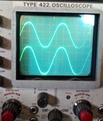
No problem getting a full voltage sine wave (100hz, 500mvac) out, first with no bias, then with 16mv. I was getting 15vac at the speaker out. See attached scope trace.*
<grin>
So I believe my next step is to hook up the remaining outputs and repeat this test (sine wave in, no load, no bias first, then 16mv bias). Measure voltage drop across each emitter resistor to check current sharing.
If it passes this, replace the current limiters with regular fuses and try the same tests with a dummy load.
So the one question that remains is whether or not the MCM 2SD424 is really good? At 50hfe, it does match gain with the others nicely. But I'll wait for the smart guys to weigh in with their opinions before I install it.
*Upper trace (ch1) is input wave, lower trace (ch2) is at speaker out.
Scope settings were: 2ms/div and .05vdc (ch1) and 1vdc (ch2). 10x probe.
Attachments
Last edited:
Thermal tracking should not be a problem in the LTP input stage if there is no heat source near it. Both transistors in the diff pair run at constant average current with the same voltage across them. Since they are in the same environment, they will stabilize at very nearly the same temperature and remain there.
Thanks Steve.
Thermal tracking should not be a problem in the LTP input stage if there is no heat source near it. Both transistors in the diff pair run at constant average current with the same voltage across them. Since they are in the same environment, they will stabilize at very nearly the same temperature and remain there.
Hi Steve,
What is your procedure for matching transistors for LTP?
David.
Hi Steve,
What is your procedure for matching transistors for LTP?
David.
I no longer build anything. When I did, I used a curve tracer. I would run the curves around the operating current and set the voltage at the operating voltage.
Nice work Fred, looks good! Are you sure that is full output, you can just touch clipping to see some flattening and be sure you are there.
I'd say finalize all the devices before hooking up the entire output stage. I believe that the improved drivers are really needed and like the MJ15032/33 option. As I said my Adcoms have the later 5A drivers.
Do you have the MJs?
I'd say finalize all the devices before hooking up the entire output stage. I believe that the improved drivers are really needed and like the MJ15032/33 option. As I said my Adcoms have the later 5A drivers.
Do you have the MJs?
Nice work Fred, looks good! Are you sure that is full output, you can just touch clipping to see some flattening and be sure you are there.
Thanks. Not quite sure what you mean by "full output" here. This is without a load.
I'd say finalize all the devices before hooking up the entire output stage. I believe that the improved drivers are really needed and like the MJ15032/33 option. As I said my Adcoms have the later 5A drivers.
Do you have the MJs?
I do have some MJ 32/33's, though all I have for matching is my IT-18 and DVM. Still, I can probably get closer to what's in there now if you think it's important. Since I have to pull the boards out anyway to reconnect the outputs, it wouldn't be a big deal.
In climbing/mountaineering there's a condition called "summit fever" which happens when you nearly finish something long, hard and scary. With the end in sight, you start to hurry and skip steps and checks. The results are predictable. I'm trying very hard not to succumb to summit fever here and make sure I do what I need to to make sure this amp will run reliably and safely.
Last edited:
Among other things beta is effected by temperature. it is difficult to have two separate transistor thermally track. The transistors have to be placed in the same case and on the same die and be tightly matched to have good thermal tracking. So even if you could find two transistors that match perfectly by your tests, there's no guarantee that they will stay that way through temperature changes.
I have seen some manufactures thermally couple transistors together with a metal band and thermal grease to try to improve the tracking.
We can get matched pair transistors in the same case but generally the VCE is too low for power amplifier design. The ones I've looked at are around VCE 45 volts max.
One could use a cascode totem pole structure and make the upper transistors high voltage type. This way you can keep the VCE on the dif pair lower.
Does this answer your question in a very round about way?
I wouldn't say "roundabout", I would say "thorough" or "useful"! Thanks.
Thanks. Not quite sure what you mean by "full output" here. This is without a load.
I do have some MJ 32/33's, though all I have for matching is my IT-18 and DVM. Still, I can probably get closer to what's in there now if you think it's important. Since I have to pull the boards out anyway to reconnect the outputs, it wouldn't be a big deal.
In climbing/mountaineering there's a condition called "summit fever" which happens when you nearly finish something long, hard and scary. With the end in sight, you start to hurry and skip steps and checks. The results are predictable. I'm trying very hard not to succumb to summit fever here and make sure I do what I need to to make sure this amp will run reliably and safely.
I simply meant full voltage swing within a few volts of the rails - perhaps you did already but it was not clear to me from the scope traces.
The reason to go to the MJs is that they have much higher current capability and most of the techs here have commented on how these are known to blow drivers. The MJs were the factory authorized upgrade as we have been told here. I'd say that your IT-18 is good enough to get the best pair out of the bunch. I'd also give them the Vceo test. If you want to leave in what you know works, I can understand that but it is not what I would do.
As far as the diff pair go, test for output DC offset with no input applied. By this I mean don't even connect it to your generator, open circuited. The theory behind this is that even though the beta is high there is a small base current which produces a voltage drop across the DC bias resistor for the +/- diff amp inputs. Note that R2 and R6 are the same value, this is why. This is a diff amp so if there is any difference in the voltage between the +/- inputs it is amplified by the pair. If you short the input to ground this balance will be upset because there is no DC blocking cap at the input of the amp. If the diff pair are biased at equal current, and have equal beta then their Ib's will be the same. They also have to match in terms of the forward bias voltage Vbe for this operating current since their emitters are at the same voltage if they have different Vbe's then the inputs will again be imbalanced.
The best thing is if you have a pair from the same lot where they have a chance of coming from the same wafer, then they will be like twins, which is what we want.
The best thing is if you have a pair from the same lot where they have a chance of coming from the same wafer, then they will be like twins, which is what we want.
I simply meant full voltage swing within a few volts of the rails - perhaps you did already but it was not clear to me from the scope traces.
The reason to go to the MJs is that they have much higher current capability and most of the techs here have commented on how these are known to blow drivers. The MJs were the factory authorized upgrade as we have been told here. I'd say that your IT-18 is good enough to get the best pair out of the bunch. I'd also give them the Vceo test. If you want to leave in what you know works, I can understand that but it is not what I would do.
Yes, the traces were taken with ~80 volts on the rails.
I'll swap in some matched MJ's when I have the output boards out to get output TR's reconnected and install Q17.
I'll test them as you advise.
Hi Fred,
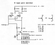
As Steve mentioned, setting up a differential pair isn't too difficult. There is the diff pair matcher I posted here before (somewhere). As for thermal tracking, put a touch of thermal compound between the two transistors, then use some heat shrink tubing to hold them together. This also creates a thermal isolation barrier between the input transistors and the environment.
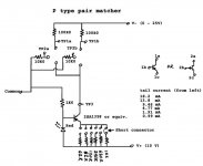
I have included diagrams for the NPN and PNP channel matchers. These work great with J-Fets as well. In fact, i am currently matching some 2SK170 J-Fets right now.
What you do is preselect transistors into rough gain / transconductance groups. From those groups, install pairs that look close and let them settle in. Measure from one collector / drain to the other. The smaller the number in millivolts, the better your match is. Notice there are selectable tail currents available. Test them close to the actual circuit current and supply voltages. I bought 1% resistors and selected matched pairs from those. These determine your accuracy, so don't use carbon film trash here. The tail current generator is fine for carbon film types.
I have also attached a detail photo of one diff pair I had done a while ago. You can see how this pair came together pretty clearly. This pair was installed in a Marantz 240 power amp. It responded well to this bit of detail work.
Hi Steve,
Curve tracers take far too much time to use on the bench for service. The advantage the jig I put together is that it removes temperature as a variable. That is unless the pair is badly mis-matched, in which case you don't want those anyway. Variable case temperature was always my biggest problem in trying to get reproducible results when testing transistors.
-Chris
As Steve mentioned, setting up a differential pair isn't too difficult. There is the diff pair matcher I posted here before (somewhere). As for thermal tracking, put a touch of thermal compound between the two transistors, then use some heat shrink tubing to hold them together. This also creates a thermal isolation barrier between the input transistors and the environment.
I have included diagrams for the NPN and PNP channel matchers. These work great with J-Fets as well. In fact, i am currently matching some 2SK170 J-Fets right now.
What you do is preselect transistors into rough gain / transconductance groups. From those groups, install pairs that look close and let them settle in. Measure from one collector / drain to the other. The smaller the number in millivolts, the better your match is. Notice there are selectable tail currents available. Test them close to the actual circuit current and supply voltages. I bought 1% resistors and selected matched pairs from those. These determine your accuracy, so don't use carbon film trash here. The tail current generator is fine for carbon film types.
I have also attached a detail photo of one diff pair I had done a while ago. You can see how this pair came together pretty clearly. This pair was installed in a Marantz 240 power amp. It responded well to this bit of detail work.
Hi Steve,
Curve tracers take far too much time to use on the bench for service. The advantage the jig I put together is that it removes temperature as a variable. That is unless the pair is badly mis-matched, in which case you don't want those anyway. Variable case temperature was always my biggest problem in trying to get reproducible results when testing transistors.
-Chris
Attachments
- Home
- Amplifiers
- Solid State
- Another high DC Adcom GFA-555