Using two bridges in that manner provides most of the benefit of using separate transformers for each channel, at much lower cost. At least this is true according to that Pass guy 😉 He used this on the A-75, I see no reason not to use it for a GC.
Use a primary fuse. Unless I missed something (quite possible) there is no reason it would blow unless it was undersized for the inrush current - use a slow blow.
The voltages seem a little low, you'll end up with somewhere around 16 volt rails. If you were loking for 35 volt rails, insulate the center taps from ground, and use a pair of transformers with the - output on one bridge and the + ouput on the other grounded. You could use two bridges on each transformer to have roughly the equivalent of the circuit that you drew.
yes
I always do that!
And I use slow blow most of the time!
Jean-Pierre
zuinig dat ik ben, gebruik ik wel een heleboel van die buiszekeringen met een houder en draaistop. !!!!!!!!
fedde said:I'd include a primary fuse!!!
Fedde
I always do that!
And I use slow blow most of the time!
Jean-Pierre
zuinig dat ik ben, gebruik ik wel een heleboel van die buiszekeringen met een houder en draaistop. !!!!!!!!
no no
I am so stupid that I supose you are talking about the drawing that I posted earlier and I finished meanwhile...
well I have 39 volts DC going to the GC'S perhaps I did something wrong or I just invented a new Coil of Tesla, but there is 39 Volts DC oresent,
and I just doubble checked it!
J-P.
BobEllis said:The voltages seem a little low, you'll end up with somewhere around 16 volt rails. If you were loking for 35 volt rails, insulate the center taps from ground, and use a pair of transformers with the - output on one bridge and the + ouput on the other grounded. You could use two bridges on each transformer to have roughly the equivalent of the circuit that you drew. [/B]
I am so stupid that I supose you are talking about the drawing that I posted earlier and I finished meanwhile...
well I have 39 volts DC going to the GC'S perhaps I did something wrong or I just invented a new Coil of Tesla, but there is 39 Volts DC oresent,
and I just doubble checked it!
J-P.
If the transformer is the 13-0-13 shown in your earlier sketch, you've made yourself a voltage doubler. You must have connected it differently than shown.
Doublers tend to collapse somewhat at higher loads. If you are in fact using the transformers shown, you may have a problem at higher outputs.
Hey, if it works...
Doublers tend to collapse somewhat at higher loads. If you are in fact using the transformers shown, you may have a problem at higher outputs.
Hey, if it works...
Re: no no
I think you're measuring the voltage acros the bridge - and + terminal. Between the center tap of the traf. and the + of the bridge should be around 16~17V, and between the center tap and the - of the bridge should be -16~17VDC. You have to have Caps. connected though.
uvodee said:
I am so stupid that I supose you are talking about the drawing that I posted earlier and I finished meanwhile...
well I have 39 volts DC going to the GC'S perhaps I did something wrong or I just invented a new Coil of Tesla, but there is 39 Volts DC oresent,
and I just doubble checked it!
J-P.
I think you're measuring the voltage acros the bridge - and + terminal. Between the center tap of the traf. and the + of the bridge should be around 16~17V, and between the center tap and the - of the bridge should be -16~17VDC. You have to have Caps. connected though.
Re: Re: no no
that's right
accross the bridge that's where i measured it,
By the way, I do not seem to have a any distortion or lack of low mids or high at any moment.... not with pioneer, audax
I do have a 'plop' sound when it is turned on, but for that I will implement one of the designs I found that eliminates that.
By the way what do ou think using a single driver for gainclones? Would there be too much hiding?
J-P.
I also bought some adjustable voltage supplies on Ebay, I may use them in one set of gc's if that would work, what do you think?
GregGC said:
I think you're measuring the voltage acros the bridge - and + terminal. Between the center tap of the traf. and the + of the bridge should be around 16~17V, and between the center tap and the - of the bridge should be -16~17VDC. You have to have Caps. connected though.
that's right
accross the bridge that's where i measured it,
By the way, I do not seem to have a any distortion or lack of low mids or high at any moment.... not with pioneer, audax
I do have a 'plop' sound when it is turned on, but for that I will implement one of the designs I found that eliminates that.
By the way what do ou think using a single driver for gainclones? Would there be too much hiding?
J-P.
I also bought some adjustable voltage supplies on Ebay, I may use them in one set of gc's if that would work, what do you think?
Re: Re: Re: no no
What are the rail voltiges (- to gnd and + to gnd)? (Just curious)
I don't have that on my GC.
It'll help if you show me the whole schematic (including the PS). But exactly the way it is right now.
Do you use the same value caps on the +V and -V? Is it possible to be the source, not the GC?
Greg
That's good.uvodee said:
that's right
accross the bridge that's where i measured it,
By the way, I do not seem to have a any distortion or lack of low mids or high at any moment.... not with pioneer, audax
What are the rail voltiges (- to gnd and + to gnd)? (Just curious)
I do have a 'plop' sound when it is turned on, but for that I will implement one of the designs I found that eliminates that.
I don't have that on my GC.
It'll help if you show me the whole schematic (including the PS). But exactly the way it is right now.
Do you use the same value caps on the +V and -V? Is it possible to be the source, not the GC?
I'm not sure what you mean.
By the way what do ou think using a single driver for gainclones? Would there be too much hiding?
Depends on the Vmax and Imax that you can get from them. Need more info about them.
I also bought some adjustable voltage supplies on Ebay, I may use them in one set of gc's if that would work, what do you think?
Greg
i will post
those readings you asked me for Greggc.....
I am looking for the post-it note that has the values, If I can't find it i will open the enclosure again,.
meanwhile I have another question:
I see caps that have 35 v, 50 v or higher.
does it matter to use a higher voltage cap than needed, I mean like extreem higher as an example I am using 50 v caps (panasonic fc) but i would liek to try thos taiwan pp caps but they seem to be rated 600 volts or more......
Does it matter?
Jean-PIerre
Re: i will post
The higher the voltage the bigger the caps will be. I'd use the lowest possible voltage, but don't go too close to the max DC that the cap can see. Add another 40-50% to the DC that the cap is cconnected to, just to be safe.
uvodee said:those readings you asked me for Greggc.....
I am looking for the post-it note that has the values, If I can't find it i will open the enclosure again,.
meanwhile I have another question:
I see caps that have 35 v, 50 v or higher.
does it matter to use a higher voltage cap than needed, I mean like extreem higher as an example I am using 50 v caps (panasonic fc) but i would liek to try thos taiwan pp caps but they seem to be rated 600 volts or more......
Does it matter?
Jean-PIerre
The higher the voltage the bigger the caps will be. I'd use the lowest possible voltage, but don't go too close to the max DC that the cap can see. Add another 40-50% to the DC that the cap is cconnected to, just to be safe.
yes yes
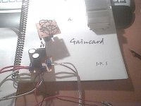
here are some pics from my third pair.....
do not pay attention to the small heatsink, when mounted inside the enclosure, there is one large heatsink that serves for both chips
lm 3875 with the cheapest components available
R's from all electronics
caps from bg micro (panasonic fc's)
to test i use basler transformers 20 v 2 placed in series
and when everything looks, feels and sounds ok, then i use the Abbott 200VA puppies
if requested I can post some gc's in enclosures (unfinished and finished) but my (short term) idea is to make some hi tech enclosure with some 3d look , I am working on it as we speak..
J-P
Attachments

I think you'll have to optimize the wireing if you don't want some oscillations happening. I'm sure you can have much shorter paths if you do PtoP or PCB.
How's the sound?
/Greg
How's the sound?
/Greg
the sound is
just great, I hear nothing abnormal
Actually it sounds a lot better than I expected.....
When I was listening to some Spanish guitar and song work from Los Lobos it actually sounded pretty scary, as if the guys were cursing to me! 😉
J-P
I am trying to get a shorter loop but on this kind of board I have problems doing that.
I am now making 2 other versions: the ultimate and your example with the 1k coming from pin 8 and 680 ohm after the 100K pot
so that I can compare a bit easier. ALl of them with the same transformer type (Abbott 200 VA from Apex jr.)
It's hard to keep those amps at home though, as I have sold my 2 earlier versions already. This time I want to keep all 3 till I have finished and compared them.
something I reaaly want to know
I udnerstand that some caps are better than others. Usually it's easy to see the difference in quality by looking at it's price.
Now I can buy Nichicon caps that say 'computer grade' for very cheap about 0.50 $ each for 1000uF 50 volts
Is computer grade not a higher quality than regular Panasonic FC ?
Jean-Pierre
(learning fo the fun of it!)
Re: something I reaaly want to know
Computer grade are a low ESR caps, but the best think is look at the data sheet of the cap you want to buy and see if the ESR is around 0.030 Ohm or less. Panasonic FC 1000uG/50V is 0.03. The lower the better. I suspect that those caps will be fine IF they are not 10 years old.
http://www.nichicon.com/english/seihin/alm_mini/list_f.htm
/Greg
uvodee said:I udnerstand that some caps are better than others. Usually it's easy to see the difference in quality by looking at it's price.
Now I can buy Nichicon caps that say 'computer grade' for very cheap about 0.50 $ each for 1000uF 50 volts
Is computer grade not a higher quality than regular Panasonic FC ?
Jean-Pierre
(learning fo the fun of it!)
Computer grade are a low ESR caps, but the best think is look at the data sheet of the cap you want to buy and see if the ESR is around 0.030 Ohm or less. Panasonic FC 1000uG/50V is 0.03. The lower the better. I suspect that those caps will be fine IF they are not 10 years old.
http://www.nichicon.com/english/seihin/alm_mini/list_f.htm
/Greg
and here is the last pic
from the conventional exnclosuresfor the gc
from now I am going a lot more exotic, something more Baume Mercier ... or better Piaget as long as PD thinks of Patek Philipe I can avoid him!
J-P
by the way, I feel it intriguing that guitar music has never sounded better here, except for on the Q 33 .......
Attachments
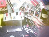
humm
my guess it that you just want to stay polite ...
I kept this one very very simple, you notice only bridge rectifier
the trannie is away from the set up, one 200VA.
I wanted to hear for myself the difference with the one that has actually a completely seperated power supply with each channel it's own rectifier
I estimate about 20 watts, maybe a bit more but I can only play at 1/6th of the volume settings, otherwise the blinds start shaking....
I am finishing your schematic Greg, this one will have stepped attenuators (I call them stepped pots because of their rimplicity, and I already have the components laid out on the schematics of Nuuk's Minimized gaunclone layout (with 2 * 432 K R's etc..)
And yes I have taken greater care so that the signal loop is extremely short!!! I did not use ANY piece of wire! not even board.
I will try to post some spec results this time so that it looks more professional to this forum.
J-P
From what I see, the wiring looks pretty neat, and the sound is up to you to tell us about. As far as the outside look, I can’t see it plus it's really a matter of personal taste. I like my amp, but don't expect others to like it too. Though by posting a picture it may give the people reading the post some ideas they may take advantage of.
One thing I wouldn’t do is use separate pots instead of step attenuators, but I knew that you’d change it as soon as you start using it.
So I second the "Looks good" part.
/Greg
One thing I wouldn’t do is use separate pots instead of step attenuators, but I knew that you’d change it as soon as you start using it.
So I second the "Looks good" part.
/Greg
- Status
- Not open for further replies.
- Home
- Amplifiers
- Chip Amps
- Another GC project