As a horn designer and builder , IMHO the 206e is really built for rear horn loading.The Qts is really too low to be effecive in a BR.
ron
ron
I have recently completed GregGC's design too, my first impressions were that it lacked bass, but i changed the input cap to a 6.8uF 100V one and it improved the bass responce to a satisfactory level and level everything out, i think the circuit sounds ok but might might need tweaking to individual taste?
Im using Cerwin vega E312's so they tell me loud and clear if theres bass or not..
I honestly have to say that i think the inverted GC i built once to test sounded a little bit breighter than this one, but i havent done an A/B comparison..
Also there is -13mV dc offset on both outputs 🙂
Im using Cerwin vega E312's so they tell me loud and clear if theres bass or not..
I honestly have to say that i think the inverted GC i built once to test sounded a little bit breighter than this one, but i havent done an A/B comparison..
Also there is -13mV dc offset on both outputs 🙂
aaargh!!!!
A few weeks ago I followed te schematics of the 'ultimate gainclonce'. It turned out to be a hit and no no 'nasty side effects'.
I could not measure any dc anywhere and the thingies (insulated on an apexjr. heatsink, that was it) played for weeks.
So when my brother in law came by yesterday he took them home after leaving behind some hard earned dollaaaars.
I made one last night, I started well after midnight till about 3 pm.
Same config, same hardware (I have stock for 5 stereo's) same toroid etc...
and every. let's say 45 seconds to one minute i get a non defined noise accompaning the music. Something i would describe as oscillating and sometomes a very present HUMM.
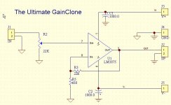
What did I do wrong??? I thought I did exactly the same thing. I use the simple schematic-ultimate gainclone with very few components (2 caps 1000uf, 2 resistors 680 & 22k and one pot 22k)
when there is no disturbing noise, the sound itself is fantastic, even when connected to a portable cd player. hi, mid and bass are, I think, very much perfectly combined...
Jean-Pierre
A few weeks ago I followed te schematics of the 'ultimate gainclonce'. It turned out to be a hit and no no 'nasty side effects'.
I could not measure any dc anywhere and the thingies (insulated on an apexjr. heatsink, that was it) played for weeks.
So when my brother in law came by yesterday he took them home after leaving behind some hard earned dollaaaars.
I made one last night, I started well after midnight till about 3 pm.
Same config, same hardware (I have stock for 5 stereo's) same toroid etc...
and every. let's say 45 seconds to one minute i get a non defined noise accompaning the music. Something i would describe as oscillating and sometomes a very present HUMM.
What did I do wrong??? I thought I did exactly the same thing. I use the simple schematic-ultimate gainclone with very few components (2 caps 1000uf, 2 resistors 680 & 22k and one pot 22k)
when there is no disturbing noise, the sound itself is fantastic, even when connected to a portable cd player. hi, mid and bass are, I think, very much perfectly combined...
Jean-Pierre
I would think that that might be external HF noise. Put your DSS cordless phone or the cell phone when it rings next to the amp and listen. I would put an input RC LF filter to cut all the HF nastiness that comes from the input. If your IC is well shielded and the caps are of a low ESR type and close to the IC you should be fine. Didi you change the speaker cable? Is your grounding done the same way as before? Check the wiring again.
I will go over it
again..
the same caps (digikey's) panasonics
i will check it in a few minutes
the LM3875 are all TF's so all insulated and mounted on the 8 by 5 by 1/2 heatsinks they are not even close to getting warm!
Let me see and tryg to find out what it is!
thanks!
Jean-Pierre
again..
the same caps (digikey's) panasonics
i will check it in a few minutes
the LM3875 are all TF's so all insulated and mounted on the 8 by 5 by 1/2 heatsinks they are not even close to getting warm!
Let me see and tryg to find out what it is!
thanks!
Jean-Pierre
I think I may have found it
i checked everything and remembered that the caps WERE indeed different!
I though I had used panasonics but they were nichicon 1000 uf 50 volts
now I used nichicon again and the problem seems to be less .there
but still after a while I get distortion when the sound gets dynamic....
and once in a while i get some oscillation
must have something to do with the shielding you think?
OK, I keep looking!
Jean-Pierre
Jean-Pierre,
Check the PS also. Measure all the voltages of the PS. Is the shielding as good as the previous one?
Greg
Check the PS also. Measure all the voltages of the PS. Is the shielding as good as the previous one?
Greg
I had to stop last night...
too nervous!
I am going to look at every thing, every connection and the shielding of the ps tonight!
I tried the panasonics as well as the nichicon's and when there is no distortion or any other noise, I like the nichicons more.
Jean-Pierre
too nervous!
I am going to look at every thing, every connection and the shielding of the ps tonight!
I tried the panasonics as well as the nichicon's and when there is no distortion or any other noise, I like the nichicons more.
Jean-Pierre
Jean-Pierre,
Did you try adding a low-pass RC filter at the input. Just to see if that is/isn’t HF coming from the input/source?
Did you try adding a low-pass RC filter at the input. Just to see if that is/isn’t HF coming from the input/source?
all though
I tinker a lot (made my own video projector and other stuff) I am rather inexperienced in electronics so I have no basic knowledge how to make a filter like that, however I think that that could solve the problem, but.....
could exterior factors start interfering after a minute or so.... would they not start messing things up right away?
Jean-Pierre
http://www.diyaudio.com/forums/showthread.php?postid=279023#post279023
Take a look at R1/C1. That is LF Filter. Use 10k/100pF. Connect them directly ont the RCA connector of the amp.
My concern is that that interference signal was not present before, or if it was, the housing of the amp you had before was doing better job shielding the amp. So if you have different type of housing now, that very well can be the problem.
Try adding R1/C1 to your amp and see if you get some improvement. Another thing to try would be to bypass the 1000uF caps with 47nF. On each 1000uF connect 47nFcap in parallel.
Let see if you get any improvement.
ok i did everything you suggested except for the
very last option the bypassing
still the same,
the time of clean music seems to reach about 3 to 5 minutes then it starts to slightly crack and then the louder humm comes forward and pushes all the other sound to the back......
very last option the bypassing
still the same,
the time of clean music seems to reach about 3 to 5 minutes then it starts to slightly crack and then the louder humm comes forward and pushes all the other sound to the back......
everytime I
turn the power off and on the sound is back to perfect for 3 to 5 minutes.....
it truly drives me crazy
J-P
turn the power off and on the sound is back to perfect for 3 to 5 minutes.....
it truly drives me crazy
J-P
Re: everytime I
Sounds like a capacitor that's bad or backwards. Check if any of them gets warm. Is the problem evident in both chanels at the same time? Do you have input cap?
Does it hapen if there is no input signal. Turn it on donCan you show me the exact sch. of the amp?'t play any music and see an see if the noiseigoing to appear.
Did you mesure the powersupply voltages when no input signal is present (when you first tun the amp on and after it starts making all the noise?
It could be a bad solder joint too.
Measure the voltages please.
uvodee said:turn the power off and on the sound is back to perfect for 3 to 5 minutes.....
it truly drives me crazy
J-P
Sounds like a capacitor that's bad or backwards. Check if any of them gets warm. Is the problem evident in both chanels at the same time? Do you have input cap?
Does it hapen if there is no input signal. Turn it on donCan you show me the exact sch. of the amp?'t play any music and see an see if the noiseigoing to appear.
Did you mesure the powersupply voltages when no input signal is present (when you first tun the amp on and after it starts making all the noise?
It could be a bad solder joint too.
Measure the voltages please.
Sounds like a capacitor that's bad or backwards. Check if any of them gets warm.
Checked them = nothing gets warm, even the LM feels cold!
Is the problem evident in both chanels at the same time?
I started with only one channel this time, so I h cannot answer that one
Do you have input cap?
I used " the ultimate gainclone schematic, second time.
Does it happen if there is no input signal. yes and no, as long as there is no signal everything stays quiet but when the music arrives then after 3 to 5 minutes i get the crackling followed by hummmmmm...
Turn it on donCan you show me the exact sch. of the amp?
sure, here it is...
't play any music and see an see if the noiseigoing to appear.
Did you mesure the powersupply voltages when no input signal is present (when you first tun the amp on and after it starts making all the noise?
toroid power ingoing is 41 volts , after the bridge it is 60.5 volts
It could be a bad solder joint too.
I checked them so many times i had to replace the LM because I broke off some tips.....
\
Measure the voltages please.
I will do so and I will also measure the dc offset. now that I found out how to do it ( with a 10 ohm R)
Gee, I must have been very very lucky with the first amp 2 channels, I built it, connected it and it played right away. This time it seems like climbing the Kilimanjaro!
Jean-Pierre
yes
Sounds like a capacitor that's bad or backwards. Check if any of them gets warm.
Checked them = nothing gets warm, even the LM feels cold!
Is the problem evident in both chanels at the same time?
I started with only one channel this time, so I h cannot answer that one
Do you have input cap?
I used " the ultimate gainclone schematic, second time.
Does it happen if there is no input signal. yes and no, as long as there is no signal everything stays quiet but when the music arrives then after 3 to 5 minutes i get the crackling followed by hummmmmm...
Turn it on donCan you show me the exact sch. of the amp?
sure, here it is...
't play any music and see an see if the noiseigoing to appear.
Did you mesure the powersupply voltages when no input signal is present (when you first tun the amp on and after it starts making all the noise?
toroid power ingoing is 41 volts , after the bridge it is 60.5 volts
It could be a bad solder joint too.
I checked them so many times i had to replace the LM because I broke off some tips.....
\
Measure the voltages please.
I will do so and I will also measure the dc offset. now that I found out how to do it ( with a 10 ohm R)
Gee, I must have been very very lucky with the first amp 2 channels, I built it, connected it and it played right away. This time it seems like climbing the Kilimanjaro!
Jean-Pierre
I forgot the schematics
sorry, here it is..
the only thing I changed (from the very beginning) is the pot. The value I use is 25 K.
For making the ground stars I use very small copper washers where every wire (cap etc..) is safely soldered onto. I make 2 stars and they are connected to each other.
I have used 3 different sources to test now : 1) portable cd player, 2) Pioneer cd player (25 disc changer) and 3) a very very cheap dvd player
the best sound comes from the cheap dvd player but the result after a few minutes is always the same whatever source it comes from .... crackling followed by Hummmmmmmmm
Attachments
Thanks for the sch.
Let see what you measure as a DC output and rail voltages as the amp starts making noise.
Does the pot position afect the noise in any way? I'd put a 22k to 47k resistor from +in (pin 7 to gnd) just to make sure that the pot is OK and it provides constant gnd path for +in.
Let see what you measure as a DC output and rail voltages as the amp starts making noise.
Does the pot position afect the noise in any way? I'd put a 22k to 47k resistor from +in (pin 7 to gnd) just to make sure that the pot is OK and it provides constant gnd path for +in.
ok
the pot position does not make any difference.
I replaced the pot with a 50 k R ... no difference.
I can do this because all the sources come with a volume pot
I have to start all over again cause I ruined 2 LM's in the last 36 hours due to pin breakage....
J-P.
the pot position does not make any difference.
I replaced the pot with a 50 k R ... no difference.
I can do this because all the sources come with a volume pot
I have to start all over again cause I ruined 2 LM's in the last 36 hours due to pin breakage....
J-P.
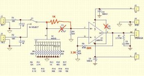
Refined Sch.
Today decided to do some experimenting with values and sch. changes.
Found that removing the cap and keeping the gain just above 20 gave the best results (base and HF balance). More base and the highs are more refined.
The 1k resistor keeps the DC offset at the output to a nice low level when the attenuator is at low levels. With the shown res. values (had to decrease them to 3.3k/68k to keep the offset low) the DC offset is in single digits at all levels but the highest volume setting (it's around 25mV at max. volume).
Found that gain at just above 20 gives more refined highs and deeper base than gain of 30.
C6 was never installed on the first place. Didn't needed. So, the less parts the better.
So, I think, for my taste this is a better performing version of the amp. No DC should be present at the input of the amp though.
Attachments
- Status
- Not open for further replies.
- Home
- Amplifiers
- Chip Amps
- Another GC project