Hi Audiophilenoob,
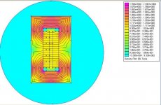
Once you get familiar with femm you can play with variables to see what it takes to get the 1 Tesla field you want. I've attached a quick femm simulation of a one inch magnet and half inch gap - it gets your 1 Tesla strength. The steel is thicker than it needs to be. I've got 2" you can probably cut it back to 1.5". If you e-mail me, I'll send you the femm file to play with. It's probably easier to start with this than the examples you get with the program.
WRT to what you are calling "electrical efficiency": I really think it is nothing more than reducing total driver impedance seen by the amp so the amp delivers double the current and hence double the power.
For example: the NeoPro5i produces 102db when you apply 2.83 volts. The driver has a built in transformer whose turns ratio produces an impedance of 7 ohms. Amplifier Power = E**2/R = 2.83**2 / 7 = 8/7 = 1.14 watts.
If you take two drivers and put them in parallel you get a total impedance of 3.5 ohms. If you apply the same 2.83 volts across 3.5 ohms you get: P = E**2 / R = 2.83**2/ 3.5 = 2.28 watts applied to the two drivers.
That is a 3db increase in power applied to the drivers.
You would get the exact same 3db increase in applied power if you had two "bare" ribbons in series and a single transformer whose turns ratio is calculated to produce an impedance of 3.5 ohms.
This increase of 3db in applied electrical power is in addition to a 3 db increase in acoustic efficiency caused by the fact you have double the area. The total is a 6db increase output. Half of this is caused by acoustic efficiency increase the other half is cause by the fact that you have doubled the power coming out of the amplifier.
Regards,
Denis
Attachments
Audiophilenoob,
An 81" long, 0.5" wide 5 micron aluminum ribbon with 1 T gap flux would conservatively have above 105 db/watt efficiency and 106 db @2.83v sensitivity. About 1 ohm resistance and 0.39 grams. Since this is a linesource, it would only lose 3db per doubling in distance, and hence play louder at the listener when compared to point-source speakers. A short waveguide could be used to increase efficiency 3-4db at the cost of more limited directionality.
This level of efficiency would likely require a magnet circuit different from Dhenery's. Without the correct motor, you will also lose audio quality. The highest effiency design will not be the best sounding design, nor will it have the highest resolution. I always put my money on quality vs. quanity in DIY.
For the absolute best sound you cannot use a transformer. A 1 ohm resistive load can be handled by many amplifiers.
Significantly lower ribbon impedances, as mwmkravchenko noted, require special DIY amplifiers to avoid the phase shifts of transformers. Apogee midrange ribbons, for example, have a 0.1 ohm resistance.
THANKS for that Dhenry... looks good to me thus far...
is that steel 1.5"x 1.5"??? or 1.5" by .5"?
Linesource... by wavelength guide you mean a wooden half round piece that's attached to the front of the ribbon to give it directionability?
If so I actually had planned on that somewhat...
Could i not still seperate the ribbons into sections... sorry to keep returning to this... but it seems like the best solution to keep the gap flux high.....
what kind of magnetic circuit would I need? how do I keep it 1 T as Dehnry's diagram shows?
I know that it might not have the BEST sound... but if I like the sound of the test ribbon that's all I want really...
I really don't know how to make an amplifier... I've seen kits and such... but I would really need to know something to build a 1 ohm direct drive... or I could pay someone on here to build one... which is a possibility I won't rule out
if I can achieve it with one long line... that would be ideal... as long as using those "guides" adds it to around 110 db of efficency...
if that seriously degrades SQ... I can remove them... 105 db is enough... or it SHOULD be enough since I'm goign active...
the long line is ideal... and if I can somehow cut down on magnet costs... that would rock as well...
right now it's up to $850 in magnets for EACH 81" ribbon... which is a little over my budget...
like I said... I only need these to go down to 2khz-2.5khz... could I decrease the depth of the magnets??? like instead of .5" deep by 1" into the gap... how about .25" deep x1" into the gap?
WOW thanks Dhenry... I figured out ... this program is easy to use!!!!!!!!!!!!!!
here's my model
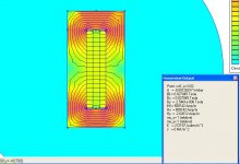
using 1.5"x1.5" steel... with
If I move down to .5" thick Neodmynium I still get a .82 telsa field...
make sure I did this right... the dialogue in the attached pic is a click on 0,0 in the field
here's my model
using 1.5"x1.5" steel... with
If I move down to .5" thick Neodmynium I still get a .82 telsa field...
make sure I did this right... the dialogue in the attached pic is a click on 0,0 in the field
Attachments

I tried doing side shots... and guessing as to what the extra bracings will do...
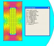
the first one on the left in the pic... is a 4 stacked magnet... so 1" thick by .5" deep
the second one is 1" deep, by .5" thick....
as you can see the 1" wide one has the higher magnetic field... around .83 telsa
the first one on the left in the pic... is a 4 stacked magnet... so 1" thick by .5" deep
the second one is 1" deep, by .5" thick....
as you can see the 1" wide one has the higher magnetic field... around .83 telsa
real quick note...
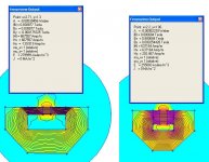
I've been modeling a lot of these sims... and I did a profile sim with U-shaped steel... and the flux in the gap is 0.86 T... good enough I think... and it reduces the magnet costs back to something MANAGABLE...
it's 4 stacked magnets every .75"... which makes a 1" depth...
1 telsa from Dhenry's model but on a profile model with U circuit it's .86
and I'm going with the waveguide...
shoudl work out well...
continous ribbon also... I also believe I can get by with 1" U steel... (maybe trim the back to .5" steel... I can't imagine what these will weigh though... 150 lbs???
Question:
When you place the magnets where do you place the poles... obviously the two pieces of steel attract each other... but what exactly do you do when you have a bunch of small magnets
is one side of steel ALL north... and the other ALL south?? or do you switch off every placement of magnets going from north to south etc?
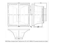
LineSource said:Example wave guide, called compact horn by SA. From SA Compact Ribbon (planar driver). Used to increase efficiency at the cost of more controlled dispersion.
would a more simple 1/2 round or quarter round trim piece like Dhenry and others have used do the same thing?
Audiophilennoob,
A modest diameter quarter round is used to reduce the edge diffraction effects of the pole piece. It will not noticeably increase efficiency. Diffraction is the bending of waves around small obstacles and the spreading out of waves beyond small opening like the pole pieces of a ribbon. When a wave hits a sharp edge, different frequencies will bend at different rates, and this "smears" the image.
Personally, I would not use a waveguide/compact-horn as it often compromises the imaging. A quarter round, or angled bezel often gives the best sound. Quality vs. quantity.
LineSource said:Audiophilennoob,
A modest diameter quarter round is used to reduce the edge diffraction effects of the pole piece. It will not noticeably increase efficiency. Diffraction is the bending of waves around small obstacles and the spreading out of waves beyond small opening like the pole pieces of a ribbon. When a wave hits a sharp edge, different frequencies will bend at different rates, and this "smears" the image.
Personally, I would not use a waveguide/compact-horn as it often compromises the imaging. A quarter round, or angled bezel often gives the best sound. Quality vs. quantity.
I see now... yea I won't use a waveguide now I guess
well using a U-shaped profile circuit I can acheive .85 T in the field gap across .5"... what would the efficency be at this?
Question to Dhenry:
how does those large gaps between the ribbon segments sound??
I can achieve a .85 T across a .75" gap with my magnets and using you circuit...
that would drastically increase efficency over the U-shapped design
however sectioning the ribbon would have 2" gaps between them all.. which definitely isn't ideal
A continuous line source with u-shaped steel would at 80" long would weigh around 400 lbs
not really doable... but I'm thinking of section those at just one point and having 2 40" sections but still 200 lbs is way over what I want...
Alright...
it seems that doing a U shaped profile is the "lightest" way to go ...
Each one will weigh around ... my guess... 150-200 lbs for the whole 80" line.... but I'm thinking about cutting that to 60" just for ease of installation...
what kind of vertical dispersion can be expected from a line source?
Linesource:
what was the method you used for keeping a DIY ribbon that's not sectioned within the magnetic field???
Vertical Dispersion??
WHat vertical dispersion? Slim to none. A line source has about 15 to 20 degree vertical dispersion. THat's the trade off when you create a vertical air pressure source. THe dispersion is greater on the horizontal plane than on the vertical. It is also a benefit when you think about the minimised floor and ceiling reflections.
MArk
Re: Vertical Dispersion??
what kind of vertical dispersion would a single 16"-20" long ribbon have without being in a line source?
mwmkravchenko said:WHat vertical dispersion? Slim to none. A line source has about 15 to 20 degree vertical dispersion. THat's the trade off when you create a vertical air pressure source. THe dispersion is greater on the horizontal plane than on the vertical. It is also a benefit when you think about the minimised floor and ceiling reflections.
MArk
what kind of vertical dispersion would a single 16"-20" long ribbon have without being in a line source?
- Home
- Loudspeakers
- Planars & Exotics
- Another DIY Ribbon thread