Fixed it!...by adjusting the VAS TPC 🙂 it just needs a few refinements as I'm still seeing a very slight peak at the square waves.

Are you seriously?(Ideas taken from Bigun and Bory's design).
Attachments
try speeding up the feedback signal at a high frequency.I'm still seeing a very slight peak at the square waves.
maybe the power went down...Fixed it!...by adjusting the VAS TPC
...continuing with my simming and applying corrections. I've decided to change the input transistor into one with a higher gain (2SA1015)...replaced feedback compensation with a new scheme to better help linearization of the loop gain. Could C11 and R24 qualify as progressive correction?
Henk, I put 3k9 instead of 3k6 in the bootstrapping in order to make the component value much easier to find in our locality (for local DIY'ers). To my knowledge the preferred ratio of these resistors falls at 1:1.5/2 into which the bottom resistor should be of higher in value. There"s a discussion about the effect but I would not go into the depths of this pairing method. I still do think it falls under the circuit topology in use (P3A had them in 1:1 ratio).
The driver currents looks pretty high compared with the other CFP's I've simmed, most had it set at around 5-6ma.
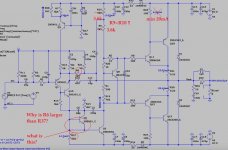
Good catch on R37! my fault actually. Originally there are two resistors in place, one placed between collector and base of Q5 and one was connected in series with the minus rail just below Q5 emitter.
The square wave simulation at 20KHz doesn't look fulfilling, or can these be ignored and check with the final hardware instead? I do know sim results are ideal but may not actually match with results from a real hardware test.
This newer configuration makes THD lower, but the trade off was a decrease in H2 making it having just a little over (in gain) with H3.
Albert


Henk, I put 3k9 instead of 3k6 in the bootstrapping in order to make the component value much easier to find in our locality (for local DIY'ers). To my knowledge the preferred ratio of these resistors falls at 1:1.5/2 into which the bottom resistor should be of higher in value. There"s a discussion about the effect but I would not go into the depths of this pairing method. I still do think it falls under the circuit topology in use (P3A had them in 1:1 ratio).
The driver currents looks pretty high compared with the other CFP's I've simmed, most had it set at around 5-6ma.
Good catch on R37! my fault actually. Originally there are two resistors in place, one placed between collector and base of Q5 and one was connected in series with the minus rail just below Q5 emitter.
The square wave simulation at 20KHz doesn't look fulfilling, or can these be ignored and check with the final hardware instead? I do know sim results are ideal but may not actually match with results from a real hardware test.
This newer configuration makes THD lower, but the trade off was a decrease in H2 making it having just a little over (in gain) with H3.
Albert
Are you seriously?
When I mentioned 'taken' this means in my own interest and applied accordingly to what I found acceptable in simulation based on my own understanding of the audio criterion. I'm just making sure that we are having a meeting of minds. 😉 I'm no designer, but I could qualify as a patchwork artist..he he
Last edited:
I've decided to change the input transistor into one with a higher gain (2SA1015)
It does not affect anything, they replaced and replaced - so far it makes no difference....
No, this is one of the Miller correction options with worse transient characteristics, because covers not 1 amplification stage but two, it is used when it is not possible to stabilize the growth of the feedback depth at high frequencies.Could C11 and R24 qualify as progressive correction?
Henk, I put 3k9 instead of 3k6 in the bootstrapping in order to make the component value much easier to find in our locality (for local DIY'ers).
OK, no problem.
To my knowledge the preferred ratio of these resistors falls at 1:1.5/2 into which the bottom resistor should be of higher in value. There"s a discussion about the effect but I would not go into the depths of this pairing method. I still do think it falls under the circuit topology in use (P3A had them in 1:1 ratio).
I do not understand who is able to conduct such discussions, the capacitance in the amplifier must be connected to a high point, which is at the 1/2 point.
The square wave simulation at 20KHz doesn't look fulfilling, or can these be ignored and check with the final hardware instead?
with such a transitional characteristic, I want to cry ....
This is a big misconception. Simulation describes 98% of all processes occurring in a real amplifier.I do know sim results are ideal but may not actually match with results from a real hardware test.
Attachments
not a very good solution to direct the input stage current to the base of the main voltage amplifier in the circuit, so there will be more distortion ...Good catch on R37! my fault actually. Originally there are two resistors in place, one placed between collector and base of Q5 and one was connected in series with the minus rail just below Q5 emitter.
I did...ahaha, 😆with such a transitional characteristic, I want to cry ....
but wait...I'm on it and its looking a little better...
Last edited:
Do you have a recommendation..🤔 feel free to write it down in the schematic..🙂not a very good solution to direct the input stage current to the base of the main voltage amplifier in the circuit, so there will be more distortion ...
Albert
so far just modeled your ideas...Do you have a recommendation
need to come up with something to put everything in order...
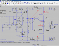
the attachment shows the futility of using shiklai assembly as input cascade in your design.
Attachments
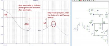
The reason for the lack of gain of the input stage, internal negative feedback through R24 (22kΩ)/
The reason for the hump, as I wrote earlier, is the insufficient Miller correction level, in addition, the unity gain frequency exceeds 10 MHz, and the depth of negative feedback at a frequency of 20 kHz is more than 30 dB, which leads to dynamic distortion.
The reason for the hump, as I wrote earlier, is the insufficient Miller correction level, in addition, the unity gain frequency exceeds 10 MHz, and the depth of negative feedback at a frequency of 20 kHz is more than 30 dB, which leads to dynamic distortion.
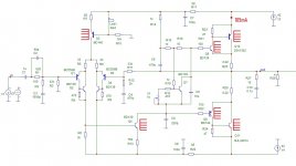
If you really want Shiklai in the input stage, ultra-linear gain and progressive correction, please ...Do you have a recommendation..🤔 feel free to write it down in the schematic..🙂
see Attachment.
Henk.
Attachments

Interesting circuit Henk, with only one compensation cap, nice! Can you share your MicroCap files? This might be a good exercise as I've used MicroCap before but I'm not so well versed with it as I'm only following examples found in the internet. I think that was version 9, I gave up at the time I was having difficulty plotting Tian probe. I do think they have now integrated Tian with version 12.
Anyway if ever I am going to build another LTP IPS amp I already drafted one circuit for that. It uses 3 pole compensation, the first time I set my eyes on such scheme was from the designs of Maestro Damir. I think that was his Little Gem amp and another one called Audiowood.
The interesting part was the add'l 10pf cap in parallel with 1M. This scheme pushes the amps ULGF without decreasing phase margin. I find the results in sim quite interesting.
However my eyes (and brain 😁) is currently fixed on the singleton amp. I have never auditioned one of this type and I've read a lot from builders that this topology is very good sounding. Popular builds here that I've known so far are, Ranchu32's 'Simple Quasi amp' Mooly's 'My amplifier designed for music' and Bigun's 'TGM8'.
I was hoping I could fix the singleton design..I will try to revise it..possibly lose the cfp input configuration and I will try to simplify VAS scheme...the challenge that I'm seeing with singleton topology was setting bias balance another thing was dc offset. It is so difficult to come up with an almost microvolt level.
Thanks for sharing your circuit.
Albert
(The LTP IPS circuit mentioned from above, the fft windowing was in Kaiser Bessel. I find this windowing function to be having much more detailed in showing harmonics. I learned it from other members here but I do not know if the results I made was in optimal state, it does look fine I think.
Last edited:
Thanks.Interesting circuit Henk, with only one compensation cap, nice!
I think it's better for you to model this circuit in LTSpice to make sure the circuit is correct.Can you share your MicroCap files?
Yes, much better, I would say very, very much better. For Q7, you need to add a resistor to the collector so that it comes out of the clip more easily.Anyway if ever I am going to build another LTP IPS amp I already drafted one circuit for that. It uses 3 pole compensation, the first time I set my eyes on such scheme was from the designs of Maestro Damir. I think that was his Little Gem amp and another one called Audiowood.
The interesting part was the add'l 10pf cap in parallel with 1M. This scheme pushes the amps ULGF without decreasing phase margin. I find the results in sim quite interesting.
All the same, I will supplement the educational program for correction. In your case, the correction still remained Miller, and the gain without negative feedback is the same as in my version, only there are 3 significant differences:
1. to reduce intermodulation distortion, my input is limited to a frequency of 350 kHz, you have a frequency of 1.8 MHz
2. I have a shiklai gain at the input of 32dB, you have about 12dB
3. I have a voltage amplifier driver working with a current of 19mA, you have only 5mA.
you also have a frequency response on the Bode diagram at a frequency of 30-40 MHz, some kind of surge, that is, the phase changes sign - this is not good, because. this can interact with the parasitic capacitance of the montage.
In any case, you seem to understand the essence of the correction, just do not forget that the value of the depth of negative feedback (20-30dB at a frequency of 20kHz) for the standard Miller correction (single-pole) was chosen subjectively. this means that the resulting quality must be tested by comparative listening and convinced of its superiority.
Henk.
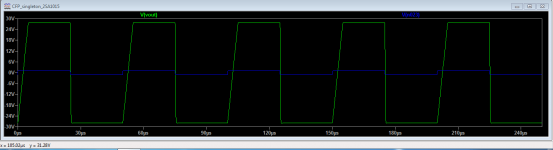
Anybody here has experienced this square wave behaviour at 20KHz? It happens only at the higher frequencies. It always appear looking tilted (leaning forward). I've made a full rework of the VAS scheme, the latest was using a PNP VAS..I've also reduced the use of cap compensation in the negative feedback line...and came up with utilizing only two miller caps in the VAS.
My..I am facing a dilemma...was it Einstein that stated 'repeatedly doing the same action again and again but expecting different results is 'foolishness'.
Ouuch..🤕
Singleton amp tilted 20KHz.
My..I am facing a dilemma...was it Einstein that stated 'repeatedly doing the same action again and again but expecting different results is 'foolishness'.
Ouuch..🤕
Singleton amp tilted 20KHz.
Attachments
Thanks.
I think it's better for you to model this circuit in LTSpice to make sure the circuit is correct.
Yes, much better, I would say very, very much better. For Q7, you need to add a resistor to the collector so that it comes out of the clip more easily.
All the same, I will supplement the educational program for correction. In your case, the correction still remained Miller, and the gain without negative feedback is the same as in my version, only there are 3 significant differences:
1. to reduce intermodulation distortion, my input is limited to a frequency of 350 kHz, you have a frequency of 1.8 MHz
2. I have a shiklai gain at the input of 32dB, you have about 12dB
3. I have a voltage amplifier driver working with a current of 19mA, you have only 5mA.
you also have a frequency response on the Bode diagram at a frequency of 30-40 MHz, some kind of surge, that is, the phase changes sign - this is not good, because. this can interact with the parasitic capacitance of the montage.
In any case, you seem to understand the essence of the correction, just do not forget that the value of the depth of negative feedback (20-30dB at a frequency of 20kHz) for the standard Miller correction (single-pole) was chosen subjectively. this means that the resulting quality must be tested by comparative listening and convinced of its superiority.
Henk.
👍 option number two..😉
Thanks for the pointers Henk.
It seems that the initial current of the voltage amplifier driver is not enough.Singleton amp tilted 20KHz.
5mA is not enough.
.
- Home
- Amplifiers
- Solid State
- Another CFP output design attempt.