Hi,
I took some pics of my bridge parallel amp and here it is: http://www.geocities.com/jojod818/index.html
JojoD
I took some pics of my bridge parallel amp and here it is: http://www.geocities.com/jojod818/index.html
JojoD
GreGC,
Thanks for the kind words, the amp is easy to implement and up to this time, a trouble free amp. 🙂
JojoD
Thanks for the kind words, the amp is easy to implement and up to this time, a trouble free amp. 🙂
JojoD
HI , How hard was it to match the components? Its seems here that this matching is what causes the most headaches when building this type of configuration...almost nobody here has accomplished this without the servos in case of the LM3886......please helps us out
avenger,
Please bear with me on this but here it goes.
When I was building my bridge parallel, I was too lazy to include the dc servo but not that lazy in matching my components. The resistors for example are 5% tolerance! So I have to measure them carefully with a DMM, that is the reason why I bought a lot of them but they are very cheap. Even the 0.1ohms 5 watt resistors are 5% tolerance so I bought a lot. I then pick the ones with the closest values and used them in my non-inverted pcb for the 549 (see my website). I wired it up, and couple it to a DRV134 for the input. Guess what? the whole amp heats up with a load!
I then said to myself, maybe I need the servos after all , but there was this basic circuit in AN1192 that uses dc blocking caps instead of servos. I desoldered one leg of the 1Kohm resistor (going to ground) and insert a small 22uf electrolytic and my problems were solved! 😎 No more heat dissipation without load, even with a load without volume.
I still can't believe that a single cap is all I need to clear that output. I tried it in a single 549, without the cap I measure 0.005V dc offset and with the cap I can barely measure a 0.001V. At a 20mV setting I can measure a 0.01mV dc offset which in my book is a very outstanding offset. 😀
I urge you to try it, I never thought a chipamp in such a configuration can handle a lot of power before but now I have proven to myself that sometimes simple things can be good, and in a diyer's hand, can be better.
Best regards,
JojoD
Please bear with me on this but here it goes.
When I was building my bridge parallel, I was too lazy to include the dc servo but not that lazy in matching my components. The resistors for example are 5% tolerance! So I have to measure them carefully with a DMM, that is the reason why I bought a lot of them but they are very cheap. Even the 0.1ohms 5 watt resistors are 5% tolerance so I bought a lot. I then pick the ones with the closest values and used them in my non-inverted pcb for the 549 (see my website). I wired it up, and couple it to a DRV134 for the input. Guess what? the whole amp heats up with a load!
I then said to myself, maybe I need the servos after all
, but there was this basic circuit in AN1192 that uses dc blocking caps instead of servos. I desoldered one leg of the 1Kohm resistor (going to ground) and insert a small 22uf electrolytic and my problems were solved! 😎 No more heat dissipation without load, even with a load without volume.I still can't believe that a single cap is all I need to clear that output. I tried it in a single 549, without the cap I measure 0.005V dc offset and with the cap I can barely measure a 0.001V. At a 20mV setting I can measure a 0.01mV dc offset which in my book is a very outstanding offset. 😀
I urge you to try it, I never thought a chipamp in such a configuration can handle a lot of power before but now I have proven to myself that sometimes simple things can be good, and in a diyer's hand, can be better.
Best regards,
JojoD
IM not sure i follow..
Which is the 1k resistor going to ground?
Which figure in AN-1192 were you looking at there?
Which is the 1k resistor going to ground?
Which figure in AN-1192 were you looking at there?
also did you use the exact schematic as in your second post? with the balanced input? how does it sound?
im planning on building an identical one this weekend as i just got the transformers 🙂 so im just trying to iron out details so the project goes as smoothly as possible!
Thanks,
Matt
im planning on building an identical one this weekend as i just got the transformers 🙂 so im just trying to iron out details so the project goes as smoothly as possible!
Thanks,
Matt
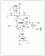
I use the drv134 for the input. Now, consider the schematic below, it's a non-inverting version from the datasheet. I build 2 pairs of this wherein each pair is in parallel. Now each pair gets their input from one of the drv134's output. Simple isn't it?
The 22uf cap that saved me a lot of headache was inserted between R1 and ground.
HTH,
JojoD
The 22uf cap that saved me a lot of headache was inserted between R1 and ground.
HTH,
JojoD
Attachments
interesting! thanks for sharing that
how does it sound?
ive not heard anyone comment of the sound of one of these higher wattage amps i dont think!
how does it sound?
ive not heard anyone comment of the sound of one of these higher wattage amps i dont think!
Optical,
I cannot comment on the sound since I use it to power a sub. But power is definitely there!
JojoD
I cannot comment on the sound since I use it to power a sub. But power is definitely there!
JojoD
I dont suppose you want to give it a try out on some full range speakers and give us a run down? 
JojoD818 said:Or this one which uses a DRV134 at the input?
Will the LM4780 (60W Stereo IC) work just as well for this circuit? (Excepting the very small pin spacings.)
http://www.diyaudio.com/forums/showthread.php?postid=259365#post259365
JDeV,
Hi, my bridge/parallel gc is still working well. In fact, I never built any other amp for my sub since the b/p gc already has sufficient power to feed my sub.
I donot really have any idea regarding the LM4780, I haven't had the chance to read it's datasheet yet. 🙁
JojoD
Hi, my bridge/parallel gc is still working well. In fact, I never built any other amp for my sub since the b/p gc already has sufficient power to feed my sub.
I donot really have any idea regarding the LM4780, I haven't had the chance to read it's datasheet yet. 🙁
JojoD
- Status
- Not open for further replies.
- Home
- Amplifiers
- Chip Amps
- Another Bridge/Parallel Gainclone Question...