Something is visible also in the datasheet, but only off axis. Keep in mind that a hole is not very offensive, a bump is. The same hole appears also in the Satori midwoofer FR, a driver that is considered one of the best 6” around.
Ralf
Ralf
Looking much better! How thick is the baffle, and have you scalloped the rear side of the driver cutout? Since it is present in the nearfield at least some of it is not due to baffle geometry, but it is probably exacerbated by the baffle geometry. I had the same problem with my MW144's in my MTM. A sharp dip that was made worse by baffle geometry, a double whammy so to speak.
As ralf said a sharp dip is generally not too much to worry about, broad peaks are much worse.
Careful baffle design (if you are lucky) can help to fill in some of the dips, if you organize so that the peak you get from baffle diffraction lines up with the natural dip in the woofers response.
Tony.
As ralf said a sharp dip is generally not too much to worry about, broad peaks are much worse.
Careful baffle design (if you are lucky) can help to fill in some of the dips, if you organize so that the peak you get from baffle diffraction lines up with the natural dip in the woofers response.
Tony.
Hmmm... I did not scallop the back side of the baffle. I’ve read about that elsewhere. Does it make a significant difference? The baffle is 3/4” cheap pine plywood in this version. It was intended to be a test box. It seems it’s serving it’s purpose as I’m learning lots!
Version two is cut to rough dimensions and I had planned on routing and assembly tomorrow. This version I reduced the volume to 9.5L and changed the port tuning to 59.4 Hz. I will center and place the drivers as close together as I can manage. It might take a couple tries... Should I chamfer the back edge on the woofer? 1/4” or 1/2”?
Version two is cut to rough dimensions and I had planned on routing and assembly tomorrow. This version I reduced the volume to 9.5L and changed the port tuning to 59.4 Hz. I will center and place the drivers as close together as I can manage. It might take a couple tries... Should I chamfer the back edge on the woofer? 1/4” or 1/2”?
Yes it is a good idea to chamfer the back, I suspect at least some of that dip is due to not doing it. It will depend a bit on the driver but if it looks closed in then it is probably having a negative effect. I'd probably go with 1/2" 45 deg.
A good idea for prototyping is to have a screw on front baffle, use some closed cell foam as a seal, weather srtip is good, then you can take it off and make changes (or even completely replace). That way you could try with no chamfer, then with 1/4" and then 1/2" to see what difference (if any). it makes.
Tony.
Last edited:
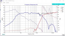
The RS150 appears to show some breakup around 1300Hz. The measurement apparently shows a couple of issues overlapping in frequency but separated in time. It's likely to be a combination of factors that should be assessed, though another approach would be to overlap the tweeter (I haven't looked at it yet). Despite the harmonic distortion concerns, the other issues would be more important.giralfino said:but only off axis
Your measurements look a lot better now, more accurate.
One thing to keep in mind is that the datasheets fro this driver are from the days it was manufactured by Usher in Taiwan. Dayton was forced to shift production when Usher shut down for a few years, and the Chinese products were all very different.
The paper drivers born at that time all have severe cone edge issues that manifest as a ~3dB dip in the passband. This is true for nearly any paper cone (when coupled to a low-loss surround) to some extent, and can be improved with edge treatments, surround reconfiguration and by hardening the cone by adding composite fibers. All of these measures bring different compromises and not all of them will totally ameliorate the dip.
As giralfino states, the Satori midwoofers have a dip there too, but not as severe, and they are considered to be very good. I am presently using the MW19 and MW13, and both of them sound absolutely amazing, I can't even hear the dip. You will find almost all owners of those drivers very happy with them, and no measures are taken to fix the dip. What's also important to check is the impedance - if you have wiggles in free air impedance around that frequency it's the driver, if you get it only when in the box, it's the box.
To your case, The ~7dB dip corresponds well with similar dips in drivers from the Chinese products - take a look at the PS-95, which has a -10 dip/peak at an irritating 2kHz on infinite baffle, which is very low for a driver of this type and makes mating to tweeters difficult. It also may be, as Tony says, a combination of baffle diffraction dip coinciding with a driver dip which means you could probably fix some of it in crossover.
My suggestion is to first finish the woodwork - chamfer the baffle edges to smooth out some of the tweeter ripple if that's not done already, also the rear of the driver hole. Then take your single-axis files, put them in Xsim, and aim for a 4th order target slope at 2.5k Fc. Don't worry about the dip as yet, there is a bump in the tweeter response at the low end that can be used to integrate the response. You will still have the dip in the final product, just less of it, hopefully a lot less.
The EEM-6 Microphone has arrived and the calibration has been uploaded to REW. These are measurement results I can live with. The microphone change is most apparent in the 10k - 20k range. Earlier in the thread a wise sage had pointed out a bump in the DBX microphone in precisely this range. The tweeter response now measures much closer to factory spec.
The take away lesson, and one I manage to keep learning the hard way is...
"Use the right equipment the first time."
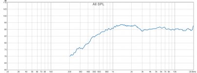
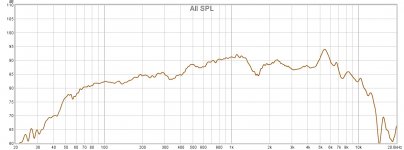
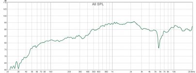
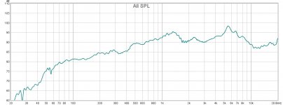
Here are the measurements from last night. Tweeter, Woofer and Drivers in Parallel. All three are taken out doors on a 7ft ladder. The microphone position is 18 inches away and on axis with the geometric center of the baffle. The mic/speaker system was not moved during these three measurements. My goal was to measure the acoustic offset of the woofer in relation to the tweeter.
The result I came up with (using Xsim) is an acoustic offset of -0.18 inches.
Please have a look and let me know if you obtain the same result.
The parallel measurement showed a very interesting null at approximately 5.7 KHz! Is this interesting or significant? How should it inform my crossover strategy?
I got curious and took several off axis measurements. I can share those results if you are interested.
After moving the speaker around... I decided to come back and invert the polarity of the tweeter to see what happened to the parallel response. I included this "bonus" test shot for the curious. Not sure if it is helpful because the speaker and microphone had been re-positioned quite a bit.
I also have Near Field Woofer and Near Field Port measurements if you are inclined.
I cannot say enough how grateful I am for for the help and expertise you all shared with me. Thank you!
***A point of order:
Now that we have achieved accurate measurements should we close the thread? I have many more questions on how to interpret and use these measurements but I'm wondering if I should start a new thread to address those topics.
The take away lesson, and one I manage to keep learning the hard way is...
"Use the right equipment the first time."
Here are the measurements from last night. Tweeter, Woofer and Drivers in Parallel. All three are taken out doors on a 7ft ladder. The microphone position is 18 inches away and on axis with the geometric center of the baffle. The mic/speaker system was not moved during these three measurements. My goal was to measure the acoustic offset of the woofer in relation to the tweeter.
The result I came up with (using Xsim) is an acoustic offset of -0.18 inches.
Please have a look and let me know if you obtain the same result.
The parallel measurement showed a very interesting null at approximately 5.7 KHz! Is this interesting or significant? How should it inform my crossover strategy?
I got curious and took several off axis measurements. I can share those results if you are interested.
After moving the speaker around... I decided to come back and invert the polarity of the tweeter to see what happened to the parallel response. I included this "bonus" test shot for the curious. Not sure if it is helpful because the speaker and microphone had been re-positioned quite a bit.
I also have Near Field Woofer and Near Field Port measurements if you are inclined.
I cannot say enough how grateful I am for for the help and expertise you all shared with me. Thank you!
***A point of order:
Now that we have achieved accurate measurements should we close the thread? I have many more questions on how to interpret and use these measurements but I'm wondering if I should start a new thread to address those topics.
Attachments
I am the first who don't measure at 1m, but 18" is probably a too short distance to be effectively considered far field for your speaker.The microphone position is 18 inches away and on axis with the geometric center of the baffle.
This info is irrelevant as you will create LP and HP filters, after you can't treat your drivers as being in parallel anymore.The parallel measurement showed a very interesting null at approximately 5.7 KHz! Is this interesting or significant? How should it inform my crossover strategy?
Are you sure? This value in my experience is pretty low.The result I came up with (using Xsim) is an acoustic offset of -0.18 inches.
Ralf
Great! 🙂 As Ralf said 18" is probably a bit too close. About the closest I have taken measurements at is 0.6M (24") , but the reason for getting closer is to get a cleaner impulse. At 7 feet up a ladder, I would think that you could easily go to 1M or even 2M (provided there are no other surfaces within that distance and still get excellent results.
You used Jeff Bagby's method for working out the accoustic distance I take it? 0.18" is about 4.5mm which does seem on the low side, around 15mm is fairly typical, unless you have a semi-horn loaded tweeter. Are you flush mounting the tweeter and surface mounting the woofer? That could definitely reduce the offset.
Tony.
The tweeter is flush mounted (5mm deep) but it also has that protruding (waveguide?) cone coming out of the center. Could this be skewing the results?
The tweeter is also offset on the baffle. I have included a screen shot of my second attempt to find the Z axis alignment. It has now changed to 10mm by my estimate using Jeff Bagby's Software and method. In the first attempt (resulting in 4.5mm) I used Xsim and did not account for tweeter offset.
I have included the screen shot of the values and results below.
There is still some discrepancy in the simulation vs the measured result. This is about as good as I could align the simulation to measured results. I can't remember if I adjusted the volume of the amplifier or gain of the signal during the final parallel measurement...
Should I give this another go with a more distant microphone placement? Should I be expecting better results?
Attachments

Z-offset offset for tweeter centered on baffle will be different from it to one side, depending on which X-axis the measurement is taken. The tweeter 'waveguide' does not change the Z-origin of the tweeter. But if your design axis is baffle center, (as it should be) ~4.5mm sounds about right as the tweeter is also further away from mic.
The combined measurement is not useful. If you measure both woofer and tweeter on listening axis without moving the mic you do not need to add the offset again as it is embedded in the result.
You do need to add the woofer nearfield though, can be done in REW else you will end up adding too much BSC. The ~20dB of baffle step you have is misleading. It is rarely more than 3dB for rooms in my country. For most speakers, 4 to 4.5dB is sufficient. Aim for a merge point around 500-700Hz.
It also appears you have some baffle effect around 1k, which seems to show as a peaking response for both woofer and tweeter, some of this is due to the very close measuring distance. There likely will be some work to be done here in crossover also, but that comes later.
I think you need at least 1 person to tell you that you can trust Jeff B's methods. There are other ways to do measurements but for your 1st time I would suggest keeping it as simple as possible and that's what his method is about.
Also, concerning AC (acoustic center) and delay:
In XSim, the woofer delay should be a positive number when the woofer AC is behind (delayed from) the tweeter. In PCD, the woofer's AC distance behind the tweeter is expressed as a negative number.
You should also know that PCD's AC number (z offset) is not the same thing as XSim's delay variable. In PCD, the z offset is the actual measured difference in the drivers' AC's. In XSim, the delay variable is the difference in path length from the mic to each of the drivers' AC's. Draw the geometry out if that doesn't quite make sense to you on 1st read.
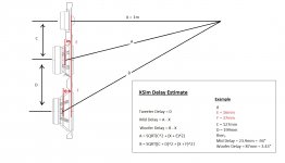
So in PCD, the program knows all the x, y, z and mic variables and then internally calculates the difference in path length. So if you change any of those things, the program recalculates and uses that new path length difference in the rest of its xo calculations. Not so in XSim. There you have to do the calculation or the measurement for a given mic distance yourself. I've added my attempt to diagram this out along with the simple equations that are necessary in XSim below (it's for a 3-way so for your purposes you just need to use half of it). This is a step that is very often missed by rookies using XSim. (I realize that I'm not taking the x variable into account here, but it's generally such a small distance that I'm just not going to worry about here.)
Now if you want to find the delay in XSim with your measurements, you don't need to worry about adding in any of the x, y, z or mic variables - simply measure each driver separately and then together without moving the mic, enter them into the program and when you have them aligned, that will be the proper delay, the correct difference in path lengths for those 2 drivers at that mic distance.
In PCD, you enter all those variables and then solve for z offset, which is a constant (well more or less). Now if that is making sense, then it follows that if you change the mic distance in PCD, the z offset should remain the same whereas if you change the mic distance in XSim the delay should also change.
Now in terms of simming your xo and getting the phase right, it makes sense to me to use a listening distance that is actually the same as your real world listening distance. Dah. So in PCD, after you get the z offset, you can simply change the listening distance variable to suit. But in XSim, your delay is locked into the mic distance you used in the original measurement. Unless you again take an extra step and re-work the equation below to isolate for the AC difference between drivers. Then you can recalculate for any listening distance you prefer. Or do the original determination in PCD and then use that AC result to calculate delay in XSim. Or maybe use VituixCAD but I haven't got around to that yet so can't comment.
Now usually I have found that when you get the z offset in PCD or the delay in XSim correct, the curves should line up remarkable well. This doesn't look like the case from what you have posted. One thing to note is that you need the correct phase info in the frd files so if your files don't include it already, extract minimum phase from them and try again.
Also, concerning AC (acoustic center) and delay:
In XSim, the woofer delay should be a positive number when the woofer AC is behind (delayed from) the tweeter. In PCD, the woofer's AC distance behind the tweeter is expressed as a negative number.
You should also know that PCD's AC number (z offset) is not the same thing as XSim's delay variable. In PCD, the z offset is the actual measured difference in the drivers' AC's. In XSim, the delay variable is the difference in path length from the mic to each of the drivers' AC's. Draw the geometry out if that doesn't quite make sense to you on 1st read.
So in PCD, the program knows all the x, y, z and mic variables and then internally calculates the difference in path length. So if you change any of those things, the program recalculates and uses that new path length difference in the rest of its xo calculations. Not so in XSim. There you have to do the calculation or the measurement for a given mic distance yourself. I've added my attempt to diagram this out along with the simple equations that are necessary in XSim below (it's for a 3-way so for your purposes you just need to use half of it). This is a step that is very often missed by rookies using XSim. (I realize that I'm not taking the x variable into account here, but it's generally such a small distance that I'm just not going to worry about here.)
Now if you want to find the delay in XSim with your measurements, you don't need to worry about adding in any of the x, y, z or mic variables - simply measure each driver separately and then together without moving the mic, enter them into the program and when you have them aligned, that will be the proper delay, the correct difference in path lengths for those 2 drivers at that mic distance.
In PCD, you enter all those variables and then solve for z offset, which is a constant (well more or less). Now if that is making sense, then it follows that if you change the mic distance in PCD, the z offset should remain the same whereas if you change the mic distance in XSim the delay should also change.
Now in terms of simming your xo and getting the phase right, it makes sense to me to use a listening distance that is actually the same as your real world listening distance. Dah. So in PCD, after you get the z offset, you can simply change the listening distance variable to suit. But in XSim, your delay is locked into the mic distance you used in the original measurement. Unless you again take an extra step and re-work the equation below to isolate for the AC difference between drivers. Then you can recalculate for any listening distance you prefer. Or do the original determination in PCD and then use that AC result to calculate delay in XSim. Or maybe use VituixCAD but I haven't got around to that yet so can't comment.
Now usually I have found that when you get the z offset in PCD or the delay in XSim correct, the curves should line up remarkable well. This doesn't look like the case from what you have posted. One thing to note is that you need the correct phase info in the frd files so if your files don't include it already, extract minimum phase from them and try again.
Attachments
I had gone ahead in my experiments by using the factory frequency response measurements and designed a crossover based on that data. The sound is surprisingly good!
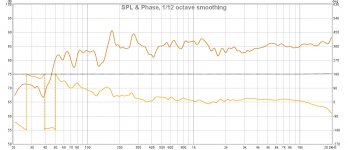
The Dayton RS150P-8A is still needing some break-in time but is rounding out nicely. I have posted a measured in room frequency response. I was in too much of a hurry this morning to do an outdoor setup.
With this measurement I was about 24 in. (61cm) away, on baffle center. The speaker was placed in the middle of the room to reduce bass gain. Smoothing is 1/12th.
My questions are now related to the crossover changes that my raw driver measurements seem to indicate. But, first the current crossover:
Tweeter:
C1=5.6 uF
L1=0.56 mH
C2=27 uF
L-Pad:
R1= 3.3 ohm
R2= 10 ohm
Woofer:
L2= 2.7 mH
C3= 6.8 uF
The sound is very nice if a little bright. In comparing them to my LSi9's (which are my only decent reference speakers), the mix is less veiled, with better imaging, very transparent. But, I miss a little of the chest in the vocals and cello's. Percussion instruments sound VERY tight. Jazz and Acoustic rock are premium with this voicing! The bride's comment was "WOW! it sounds like he's right there!"
The lack of bass response (will probably improve with break-in) makes classical, rock and electronic/ pop music sound thin and too bright. I am considering shooting for a -2 dB slope from 700-10kHz in order to give more body to vocals and keep the pop/ rock music from being too bright. Thoughts?
The new measurements seem to indicate I should take the tweeter lower, somewhere around 1.5K to get a very smooth response. At this point I am wondering, should I follow the majority advise and integrate this tweeter around 2-2.5k min? If I bring the tweeter lower, into the 1.5KHz range that would change the tweeter C1 value closer to 27uF. It seems a bit extreme.
Or... Is this questions premature to ponder considering my new baffle and box design are nearing completion?
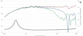
I've included the in-room measurement and the factory curves for the drivers. The new outdoor measurements of the raw drivers in this baffle are in a post above.
Thanks for helping me think this through!
The Dayton RS150P-8A is still needing some break-in time but is rounding out nicely. I have posted a measured in room frequency response. I was in too much of a hurry this morning to do an outdoor setup.
With this measurement I was about 24 in. (61cm) away, on baffle center. The speaker was placed in the middle of the room to reduce bass gain. Smoothing is 1/12th.
My questions are now related to the crossover changes that my raw driver measurements seem to indicate. But, first the current crossover:
Tweeter:
C1=5.6 uF
L1=0.56 mH
C2=27 uF
L-Pad:
R1= 3.3 ohm
R2= 10 ohm
Woofer:
L2= 2.7 mH
C3= 6.8 uF
The sound is very nice if a little bright. In comparing them to my LSi9's (which are my only decent reference speakers), the mix is less veiled, with better imaging, very transparent. But, I miss a little of the chest in the vocals and cello's. Percussion instruments sound VERY tight. Jazz and Acoustic rock are premium with this voicing! The bride's comment was "WOW! it sounds like he's right there!"
The lack of bass response (will probably improve with break-in) makes classical, rock and electronic/ pop music sound thin and too bright. I am considering shooting for a -2 dB slope from 700-10kHz in order to give more body to vocals and keep the pop/ rock music from being too bright. Thoughts?
The new measurements seem to indicate I should take the tweeter lower, somewhere around 1.5K to get a very smooth response. At this point I am wondering, should I follow the majority advise and integrate this tweeter around 2-2.5k min? If I bring the tweeter lower, into the 1.5KHz range that would change the tweeter C1 value closer to 27uF. It seems a bit extreme.
Or... Is this questions premature to ponder considering my new baffle and box design are nearing completion?
I've included the in-room measurement and the factory curves for the drivers. The new outdoor measurements of the raw drivers in this baffle are in a post above.
Thanks for helping me think this through!
Attachments
Last edited:
If you need to bring down the crossover point to 1.5KHz, you need to change the tweeter and use a more robust one. Period. The fact that you need to use more expensive crossover parts for such a low crossover point is irrelevant.The new measurements seem to indicate I should take the tweeter lower, somewhere around 1.5K to get a very smooth response. At this point I am wondering, should I follow the majority advise and integrate this tweeter around 2-2.5k min? If I bring the tweeter lower, into the 1.5KHz range that would change the tweeter C1 value closer to 27uF. It seems a bit extreme.
Ralf
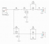
You might want to try something like the following:
- ease up on the woofer rolloff and then use a wide notch filter to attack the rise between about 700-1300Hz. (I used a parallel notch filter but you might also want to try a series one to compare.)
- then increase the steepness of the tweeter rolloff.
You are going to get a valley centered around 1600Hz (unless that's some kind of measurement anomaly) but that may be more easy to live with than what you have now.
I've attached a quick effort with XSim using the measured files you included in post #47 although I don't expect the values to be bang on - my woofer delay was a guess at .8". You may have obtained different results. If you are using XSim, make sure to turn off the System phase and turn on the phase for each driver. Then try to line those up right in the region of the xo too while still getting the best summed FR that you can. See the 2nd pic.
I added a couple of other components to fine tune the responses: C6 works as a tanking filter aimed at that little peak on the woofer between 5 and 6kHz. You can decrease the depth of the notch by adding a resitor in series with it if you want to.
And I've added another tanking filter to the tweeter circuit aimed at about 900Hz that helps to steepen the rollof which should help to keep the increasing distortion of that tweeter below 2000Hz below audibility. Both C5 and L4 can perform this function just about the same. Your choice which to use. I don't think the cap has to be an expensive one so that might end up being cheaper than a 5mH inductor.
Note that all of those tanking filters work in combination with the other component they are attached to. So if you change to values of L1, L3 or C4, you also need to change the values of other component to keep the notch in the same place.
Attachments
Last edited:
jReave,
Thank you! I was also considering a filter to knock down that peak in the woofer. (And probably will in the next version) Part of my goal with this crossover was to contrast the different results from building a crossover based on factory specs and one based on the measured response in the actual cabinets.
I have seen other projects using this tweeter down to 1,500 but I will move forward with the advise I get here and cross higher. At this point I am only waiting on the No Rez cabinet treatment from GR Research to finish the next iteration of box design.
Does anyone here have experience with the No Rez product? Are there alternatives I should consider?
It looks like a combination material. The inner similar to the old method of bitumen sheets on the walls.
The foam looks thin and is not in a good location, being on the walls, to be of much effect.
The foam looks thin and is not in a good location, being on the walls, to be of much effect.
I've used an earlier version of these products to great effect. Noise Control Panels, Flexible Mass Barrier | Pyrotek
I think this one looks like it would be the best bet. https://www.pyroteknc.com/dmsdocument/161/SORBERBARRIER-V-TDS-445IP.pdf
link to a post I made with comparison with and without. Speaker Dampening Materials. What do people use?
The product I used isn't available any more, but I think the one I put in the second link should be even better.
edit: looking further in that thread, maybe use the one in post 11 as a more realistic example of what it can do.
Tony.
Last edited:
- Home
- Loudspeakers
- Multi-Way
- Anomalous REW driver readings? 2-way design help!