That's hard to believe, without momentary plate current changes there could not be any output signal whatsoever ...
What you have in mind is that the *average* plate current does not change.
And this is what happens when the O.P measured the plate current with a moving-coil meter:
At 5Hz the needle follows the momentary current swings to some degree.
With a musical programme which contains only frequencies 50Hz and above (even with heavy bass) the coil damping does not allow the needle to follow the fluctuations and hence the meter integrates and shows just the average current, which indeed does not change much.
I've simulated the simplest class A amp in spice with a mosfet and yes the current does change 🙂
I'll scope the voltmeter and see if it's damping of the needle or something weird going on
That's hard to believe, without momentary plate current change....
He has a needle meter, somewhere. The needle won't follow audio. I don't think 5Hz is audio. Yes, 50Hz will jiggle a needle. And wear it out.
Knowing this, "normal practice" is to meter the FEED, not the tube. Between filter cap and plate transformer. He didn't say where. I'm not clear where you want to read.
It's not really clear but the needle is placed across a 100ohm cathode resistor, didnt want to have 600volt on one side of my meter, It's on the horrible schematics on the bottom right side 🙂
update
Sorry for the long wait had a few holidays and exams, 2 still to go...
I hadn't time to play with the spooky lamp but did some math, am I completely off or not?
I'm doing the same math with pentode curves, hoping for something more than 10w, will update later!
Sorry for the long wait had a few holidays and exams, 2 still to go...
I hadn't time to play with the spooky lamp but did some math, am I completely off or not?
I'm doing the same math with pentode curves, hoping for something more than 10w, will update later!
Attachments

update2
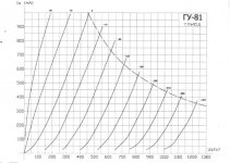
Pentode curves, pretty rough, scale too small on the datasheet.
I'll take real world measurements as I remember different currents at various Ug1, with those I'll redo the math if is somehow correct the one thing that screws me up is the RL of the transformer :/
Pentode curves, pretty rough, scale too small on the datasheet.
I'll take real world measurements as I remember different currents at various Ug1, with those I'll redo the math if is somehow correct the one thing that screws me up is the RL of the transformer :/
Attachments

Unfortunately I can't edit the original attachments but here is the "safe" alternative anyway, if an Admin wants to remove the schematic of the first post 🙂
 First post updated with new image.
I don’t see a mains transformer, so I would NEVER use this amplifier! It is against all safety rules.
Regards, Gerrit
He's using an isolation transformer for the anode supply. He doesn't show the filament transformer.
As long as it has a filament transformer I wouldn't be worried about it. It's just 2 mains transformers
instead of 1 with 2 secondaries.
G²
He's using an isolation transformer for the anode supply. He doesn't show the filament transformer.
As long as it has a filament transformer I wouldn't be worried about it. It's just 2 mains transformers
instead of 1 with 2 secondaries.
G²
The chassis is floating and hooked up to ground, separate filament transformer inside as I'm fully aware that with the direct heated cathode if everything is powered directly from mains the filaments are at mains potential for part of the sine.
Input is fully isolated too with a transformer, as the sad 20watt amp i'm using cannot drive 100+v into the grid plus the ground of the signal would be attached to cathode, thus mains...
Output is still isolated by the output transf...
Everything is contained within the chassis and if anything would touch the chassis the ground fault thingy would pop, and I will put one inside the unit, You can never be so sure about others homes and how the didnt wire the grounds...
Still if you want to check everything I'm using an "isolation transformer" (12v to 220v ups).
Dont read this in angry terms or anything, I'm fully aware of what I'm doing (power supply wise) and even wrote in the schematic dont do this if you dont know what your doing!
And still 600v is 600v, isolated or not if you touch the anode you light up, the chances your are touching something grounded to cathode in case of a standard schematic (my cathode is not on chassis) is pretty high.
I may have goofed the math tho, as I've blindly assumed a voltage transfert on the OT to speaker without calculating the current on the primary AC resistance and then that converted to the speaker, am I right?
- Home
- Amplifiers
- Tubes / Valves
- Anode current only swings positive