I've tried the Cat-5 speaker cable thing and I was pleasantly surprised in the difference it made over my previous speaker cable.
The twisted pair will have a tendency to pass really high frequency stuff better than lamp cord, for example, though we're talking waaaaay up there, well out of audible range... But somehow it did make a difference in the presentation of detail, which is something I was not expecting. There was no added harshness or glare... it was simply an increase in resolution, fine detail.
The rest of the spectrum seemed unmolested. I thought I heard some added crispness in the bass, such as with kickdrums, etc... but later proved it to be my imagination. Instead I was hearing some extra detail in the upper harmonics of the kickdrum, from the "puff" sound that is made when the drum is struck.
"This is an interesting idea, but I have 2 questions..:
1 - Won't it add graininess, now that I am used to 'quality' cable?
2 - Does 10pair refer to the type as it comes off the reel, or the fact you've run 10 pairs of conductors together??
3 - Also, yes you may pull a face here - but what about geometry? I'm really keen on using braiding or at least twisting to reduce RFI. I do not, however, wish to repeat the nightmare of making 54-conductor CAT-5 cables, as I tried once (it got too short and took weeks - it's now a nice power lead for my cdp)
Obviously, x-over out of the box will make it infinitely easier to tinker, but will it also improve the sound, as I hope?"
Hi Simon, I'm glad to help you so far.
Hey, that's 3 questions ! - ...... 😉.
1) - Ummmm, quality is a relative term, engineered by the sales department isn't it ?........... but I understand what you mean.
I regard all cables suspiciously, and more so as the price and the claims increase.
Electrically correct is electrically correct in my books, and there is no sustitute.
Not electrically correct implies electrical reactances and possibly electrical resonances and these or the products of these can become audible (transiently at least).
In my understanding and experience a low inductance and low resistance connection from the amplifier to the loudspeaker brings immediate big benefits, like the system goes harder, louder and cleaner but more relaxed at all levels.
Graininess - My experience of wide spaced thin conductors like your DNM cable is that it is not optimum.
The inductance can cause a stridency and the resistance causes a strangling and a thinning that can sift out graininess but still leaves that smashing glass character.
2) - The photos should say all.
3) - The cool thing IS the geometry.
Each of the pairs is twisted several turns per foot, and the conductors are close spaced so RF pickup should be minimal (and is in my experience).
The ten paralleled pairs exhibit 1/10th the loop inductance of each pair at the expense (?) of shunt capacitance.
Each twisted pair exhibits a characteristic impedence of around 150 ohms, so it follows that a 20 pair will give a characteristic impedence of around 7.5 ohms........According to a previous thread - Jocko, or was it Fred, did you ever do those 10pair TDR measurements I asked about ?.
I think this is a good thing too, for RF pickup reasons if none other, and I have others.
GF dropped in so must go (off to her place 😉 ) - I'll continue tomorrow
Eriic.
Let me share my findings on the harsh "sss".
Three weeks ago I replace my DIY project #1 (a JLH-amp 1996 version, no audio-grade components) with my second DIY project. (a JLH-2003 version, audio grade components).
Going through my favorite CD's I had an instant notice of the reduction in "sss".
As the power-amp had been the only component changed upgrading was the only factor which reduced sharp sss'.
Sarah Brightman 's great for hearing this.
There are 10 individual pairs inside the sheath.SimontY said:Looks cool! How are the wires arranged wthin the jacket?
-Simon
Terminating involves fanning out all the pairs, seperating all the wires into two groups of coloureds and whites, marking the strip lengths and stripping the individual insulations, and then twisting all the wires in each group so as to make two conductors.
This can take a little practice to get it right and neat looking.
20-pair takes twice as much time but is sonically better again, and gives more than enough copper.
Eric.
Hi,
The phone cable looks like a great option. I will look for some and try it out, been quite busy tho 🙁
I'm also still waiting for my Kimber 4PR back from my friend to try, which I've not yet heard with these speakers.
In the meantime, I've reduced the toe-in on my speakers, they now fire almost straight forwards. I must say I prefer it this way! The stereo image has become more vague, but I now have more emhasis on the lower mids and upper/mid bass - what I needed. THe system now has better 'boogie-factor' - it's more enjoyable to listen to, more tuneful and toe-tapping.
We'll get all the way to audio-nirvana one day, but noone said it would be easy... 🙂
-Simon
dutch diy said:Going through my favorite CD's I had an instant notice of the reduction in "sss".
As the power-amp had been the only component changed upgrading was the only factor which reduced sharp sss'.
Sarah Brightman 's great for hearing this.
it is possible that the elimination of sss' is caused by a roll-off at higher frequency for the 2nd amp?
Hi Simon,
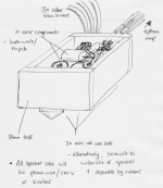
If you decide to go the telephone cable route (and I strongly recomend it), you only need to drill two holes through the back of the cabinets to get the cables into the box, and these can be easily plugged if you later refit the crossovers internally.
If you shock mount the crossover section on rubber o-rings or rubber strips or something, you can reduce microphonic effects.
Is the crossover section on a pcb and are you able to send me a layout diagram ?.
Eric.
Hi Eric,
If and when (hopefully soon) I go external I will simply remove the 4-pole Speakon socket and use that hole, it will probably be large enough for 3 sets of wire (one per driver). I will solder the cables directly to the x-over, I don't want an extra connection messing things up.
The x-over is on a PCB with large, thick copper sections, but I'd like to take it all off and resolder it point-to-point - as it is I'm adding connections for no reason other than because they gave me these boards! The kit came with a photocopied sheet of the layout (for idiots like me!), but I will need to track it down, no idea where it is.
I'm thinking of making some simple boxes to rest on the plinths or be screwed under the cabinet 'crotch' area (please see earlier pictures to understand!). I like the idea of 'isolating' them with rubber. I have some spare 18mm MDF sheet, so that's what I'll use for the boxes. Guess I'll make 'em nearly as wide and deep as the cabinet, that way I'll have room to space the components away from each other, and will have room to upgrade the remaining metal film and electrolytic caps. The only serious cap at the moment is the series tweeter, which is a lovely Maplins pp one (the one in my avatar actually!).
I think the inductors will remain the same for a while (all fat air-cored beauties), but with a large, accessible box, I can toy around with impedance correcting circuits or whatever I choose to add in the near future!
I guess I ideally need to decide on better/apt. speaker cable before doing all this, as I want to 'hard-wire' it all.
Sorry to go on about what to most DIYers is probably quite trivial!!
Cheers,
-Simon
Rambling.............
Hi Simon,
My reason for asking about layout that this is mega mission critical, and most crossover pcbs that I have seen (and improved) are hopelessly wrong.
If not done correctly, sonically nasty resonance and IMD products can result.
Perfect star grounding and star input distribution is absolutely required, and most crossovers fall sadly short of this.
Also compensation networks need to be fitted directly across the driver at the driver connections, and not back at the crossover section.
I have a very nice pair of Canton 12", dome mid, dome HF, 3 way cabinets that in factory condition are pretty good sounding, but get a touch raucous/shouty when pushed overly hard.
A momentary glance at the crossover pcb layout reveals stupid layout errors.
Once corrected (layout and RC networks) these now go louder and stay markedly cleaner, cross between drivers better (12dB slopes) and none of those little transient and mids/highs nasties that they used to have.
I know I said it already, but make sure that all cable runs are in the same direction for good coherence across the whole audio band.
This brings me to an anecdote - I work as a producer at the local community radio station on Sunday nights, involved with a Blues program.
I produce live to air guest muso performances, (set up mics, cables and outboard mixing desk, set levels and fling a copy to a hard-drive, and flick station output between my mix and the on-air desk), answer the phones, internet reseach about featured artists etc, and general station technical maintenance.
Anyway, last night I had a closer listen to the monitors in the on-air studio from the announcers position.
The desk line level monitor output (monitoring what is sent to the transmitter) feeds a domestic amplifier that drives a pair of B&O 8" 2way speakers mounted high up inside the studio facing the on-air mixing desk - these mute when the announcer goes on air.
I have always been suss with the sound of this monitor system, so last night I had a closer listen and I heard a strange 'one of the highs drivers is reversed polarity' like sound.
Within ten minutes I discovered two (bad/sloppy/ignorant)installation errors.
First error was that the speaker cables are reversed direction.
The second un-match was that the cable polarity usage was reversed - ie the striped wire for one cable was connected to amp (+), and the other channel was wired to amp (-).
Swapping polarity both ends of this cable made both cables wired the same, but opposing directions.
This helped but did not fully cure the problem - I'll fix this next week.
Eric.
Yes.millwood said:
it is possible that the elimination of sss' is caused by a roll-off at higher frequency for the 2nd amp?
Load dependant behaviour is another cause.
Cables are of course part of the load, and according to the amplifier used, different cables can cause wildly differing resultant in-room sound.
Eric.
Eric,
Hmm, fascinating stuff. I'd never thought x-over part positioning was *that* critical!
I'm gonna have to pry for more details when I get re-locating my own x-overs...
Cheers again!
-Simon
Hmm, fascinating stuff. I'd never thought x-over part positioning was *that* critical!
I'm gonna have to pry for more details when I get re-locating my own x-overs...
Cheers again!
-Simon
Hello Eric,
I notice you've been spreading the word about your phone cable on other threads too! Good stuff.
This is a quick one really. When looking for this stuff, what names does it go by? I ask, after looking through the Farnell website and getting lost in a sea of wires!
Thanks,
-Simon
I notice you've been spreading the word about your phone cable on other threads too! Good stuff.
This is a quick one really. When looking for this stuff, what names does it go by? I ask, after looking through the Farnell website and getting lost in a sea of wires!
Thanks,
-Simon
Re: Rambling.............
This line just cracked me up...
And there was me thinking the whole "directional cable" fallacy had been put to bed years ago. I don't know about yours, but my music tends to consist of AC waveforms. or do your bass electrons go in one diirection whereas your treble electrons go the other way?


Wake up!
😉
mrfeedback said:I know I said it already, but make sure that all cable runs are in the same direction for good coherence across the whole audio band.
This line just cracked me up...
And there was me thinking the whole "directional cable" fallacy had been put to bed years ago. I don't know about yours, but my music tends to consist of AC waveforms. or do your bass electrons go in one diirection whereas your treble electrons go the other way?
Wake up!
😉
Hmm, I'm technical wizard either arniel, probably why I listen with an open mind. As I see it though, the signal getting there, is more important than the one going back, [which may or may not make sense].my music tends to consist of AC waveforms
I've never listened for correct directionality myself, but many wires/cables have it marked, apparently for good reason. Many claim it is easy to hear the difference between one direction and the other. I don't doubt them. Kimber and others can now even measure cable directionality!
-Simon
marketing
Yup, companies mark direction on cable... because some gullible customers with more money/time than sense think that a directional cable must be better than one that isn't. And since they're in the business of selling the stuff, the unscrupulous one will do whatever the customer demands.
Yup, companies mark direction on cable... because some gullible customers with more money/time than sense think that a directional cable must be better than one that isn't. And since they're in the business of selling the stuff, the unscrupulous one will do whatever the customer demands.
purplepeople said:
"self-identified audiophiles", 🙂
Sounds like they are well represented here too, 🙂
SimontY said:many wires/cables have it marked, apparently for good reason.
yes, a good reason for their marketers; a bad reason for your bank account.
>Companies mark direction on cable... because some gullible customers with more money/time than sense think that a directional cable must be better than one that isn't. And since they're in the business of selling the stuff, the unscrupulous one will do whatever the customer demands.<
Not necessarily. One cable company that I know of listens to each spool of copper wire that comes from the refining and drawing plant, and marks it for directionality before shipping it out to the company that applies the insulation. One time they had a whole manufacturing run of a certain speaker cable made with the wrong directionality, because the place that molded the insulation got the markings mixed up (I think that one polarity was made with the "correct" directionality while the other polarity was reversed).
This company chose not to sell the cable, because it was wrongly made. I heard about this, signed a waiver stating that I acknowledged that this was defective merchandise, picked up most of the lot at the cost of manufacture, and use it for internal wiring in production.
Is cable directionality noticeable in blind listening? Don't know, as I haven't tried the test.
But I do know that "unscrupulous" is not a word that I would use to describe this particular cable company's actions.
jonathan carr
- Status
- Not open for further replies.
- Home
- Amplifiers
- Solid State
- Annoying solid state sound... what to do?