Actually, I'm exploring now a matter of bearing chatter (together with how parts of arm resonate) with different kinds of sensors attached to the different locations of the arm. Will put some results later. Frank Schroeder smartly got rid of chatter using string suspension. For sure, it may be used with other arm designs, including linear ones. Another type looks proper for use in tonearm: flexure bearings
Flexure bearing - Wikipedia
As in a tonearm 360 degree rotation is not needed, it simplifies matters a lot.
Flexure bearing - Wikipedia
As in a tonearm 360 degree rotation is not needed, it simplifies matters a lot.
Walter, I envy your scientific approach: mine was involuntary.
My first gimbal, with excellent SKFs, had grounding problems (taken from the arm base, relying on the electrical continuity of the whole). So I heard the chattering not as subtle sensation, but as terrific discharges on basses that almost destroyed my speakers. (the bearings conducted just during the biggest resonances)
Fixed the grounding, discharges disappeared, but I know that the bastard is still there. Since then a long path to avoid bearings drove me to these strange arms, posted on an interesting thread of Nanook
a continuation of DIY TT bearing...But now Tonearms! post # 53 54.
For what you're thinking, there you can find interesting ideas and solutions from the past.
But we're going off topic..
carlo
Little difficult for me to understand. I need time to visualize this.The stylus-to groove friction force rises between the stylus and the (virtual) pivot of the arm. If the pivot lags (the stylus moves forward in radial direction towards the record spindle), the friction force can be decomposited to a tangential force and to a radial force. The radial force will rotate the whole arm until this force component becomes zero, i.e. the drag force will be equal to the tangential force. How will the radial force move the whole arm? It will rotate the arm around the fixed stylus tip so that the (virtual) pivot moves inwards.
My observation is that the virtual pivot of the arm is not necessarily equal to the effective length of the arm, neither with the stylus-to-guiding rail distance. It can be much further away, if the guiding rail (air bearing) friction is sufficiently small.
Thanks and regards.
Flexure bearing
Hello walterwalter,
In 1984 I was the first to use Flex Pivots in my tangential tone arm. In my quest to design the perfect tangential tone arm, I have used them in all four prototypes since then. In 1984 Bendix was the only maker and they cost 35 US Dollars a piece. I bought the last pair in 2016 and the price had risen to 45 US Dollars. The field of flexure and ligament suspension goes back to well before WW2. I have a Sperry Gyro compass in my collection where the sensitive element is suspended by 18 music wires .009" in diameter.
Rate gyros are commonly supported by flexures.
Sincerely,
Ralf
Another type looks proper for use in tonearm: flexure bearings Flexure bearing - Wikipedia As in a tonearm 360 degree rotation is not needed, it simplifies matters a lot.
Hello walterwalter,
In 1984 I was the first to use Flex Pivots in my tangential tone arm. In my quest to design the perfect tangential tone arm, I have used them in all four prototypes since then. In 1984 Bendix was the only maker and they cost 35 US Dollars a piece. I bought the last pair in 2016 and the price had risen to 45 US Dollars. The field of flexure and ligament suspension goes back to well before WW2. I have a Sperry Gyro compass in my collection where the sensitive element is suspended by 18 music wires .009" in diameter.
Rate gyros are commonly supported by flexures.
Sincerely,
Ralf
Last edited:
Hi Carlo,
I have been following this thread for years and have added a couple of posts in my time. I have to say that I am very impressed with your design. Zero offset and variable overhang/effective length is definitely a novel approach.
There has been a lot of discussion as to whether your design will require an antiskate mechanism or not. As the arm moves to the right it also moves forwards. If you pull the arm forwards with stylus drag it will want to also move to the right causing a skating force. My rough calculation would suggest that the level of skating would be roughly equivalent to an offset angle of 23.5°. About the same as a 9" arm.
I haven't fully investigated this but I believe that the only type of passive arm that doesn't produce skating force is the linear trackers.
There are several myths regarding linear tracking tonearms that are repeatedly mentioned in threads on forums such as this one and in the audio press. These myths are based on supposition and are never supported by any evidence. Unfortunately you have fallen into the trap of believing one of these. You have on several occasions mentioned the "problem" of moving the entire mass of the carriage laterally using just the force applied to the stylus and have intimated that this will stress the cantilever to a damaging level. This mass-inertia effect is often referred to as "the tail wagging the dog".
The force required to move the arm laterally is supplied via the stylus/cantilever. The stylus/cantilever is connected to the cartridge by a spring (the compliance of the cartridge's suspension.) The force will cause this spring to deflect resulting in the cantilever rotating leading to a lateral tracking error. The amount of tracking error is dependent upon the compliance of the cartridge and how much damping is in its suspension, the mass/effective mass of the arm, the amplitude and frequency of the driving force (how eccentric the record is and how fast it spins). Unless the arm and cartridge are grossly mismatched the amount of this error is very low.
For example, based on a rigorous investigation that I have carried out. Take a typical linear tracking tonearm tracking a record with an eccentricity that causes the arm to move back and forth by 1mm at 33 1/3rpm. The average lateral tracking error caused by the mass-inertia of the linear arm is approximately half of that caused by the antiskate mechanism of a typical 9" pivoted arm (same cartridge). Skating is a constantly changing force that can only be compensated for to a rough average. If the record is perfectly concentric the tracking error due to mass-inertia goes away, the skating error remains.
(As an interesting aside that's a little off topic. Due to the fact that warps occur at higher frequencies than eccentricity the "tail wagging the dog" effect is actually significantly more pronounced in the vertical plane than in the lateral. This means that a conventional pivoted tonearm actually wags more vertically than a linear tracker does laterally. Of course the linear tracker also wags more vertically than it does laterally.)
This point that the tail doesn't actually wag the dog is surprisingly important for your design. Your arm pivots like a conventional arm and slides like a linear tracking arm at the same time. You have a long armtube with a large counterweight close to the pivot. The mass of this assembly is significant. This entire structure moves about 40% the distance the stylus moves. It will therefore contribute about 40% of its mass as effective mass. Plus you still have the effective mass of the arm rotating about its pivot as with a conventional arm. Adding these together will give a total effective mass that is comparable to that of a linear tracking tonearm.
Another linear tracking tonearm myth is that having different effective masses in the vertical and lateral planes is bad. It is in fact quite the opposite. As warps and eccentricity occur at different frequencies the ideal masses to cope with them are also different. Your design has higher lateral effective mass which is a good thing.
One of the things I like most about your design is that it doesn't have any pivot pointsat the headshell. Putting a bearing of any kind in this location will dramatically decrease the structural integrity of the arm resulting in loss of sound quality.
I love all the work that you have put in so far and all your detailed descriptions and diagrams.
Good luck with your build
Niffy
Please check my calculation as follows:
A hypothetical cartridge has a compliance of 10^-5 cm/dyne. 1 dyne = 10^-5 N. The peak modulation of a record groove is 40 um. Let's assume the distance between grooves is 80 um (0.08 mm). So the stylus deflection will cause 800 dyne force, that is 0.0008 N. This is equivalent to 80 mg weight force. This force will move forward the arm (pivoted or linear tracker, no matter) upon each rotation of the LP. The larger the arm pivot friction is, the more the cantilever deflects. No friction - the cantilever remains straight.
If the change of force occurs at higher frequency (like excentric record), we have to calculate with the effective mass of the arm. Then it becomes a 2nd order vibrating system (cantilever compliance, arm effective mass, frictional damping + stylus suspension damping). Horizontal excitation is disc excentricity, vertical excitation is record warp.
niffy gave a good dynamic description taking the effective mass of the arm into consideration. I neglected it in my static force calculation above.
😕 Eh, using an online calculator gave 800 dyne for 80 micrometers deflection (with a cartridge of 10^-5 cm/dyne compliance), and converted to 815 milligrams weight force. Sorry for the confusion.
Please check my calculation as follows:
A hypothetical cartridge has a compliance of 10^-5 cm/dyne. 1 dyne = 10^-5 N. The peak modulation of a record groove is 40 um. Let's assume the distance between grooves is 80 um (0.08 mm). So the stylus deflection will cause 800 dyne force, that is 0.0008 N. This is equivalent to 80 mg weight force. This force will move forward the arm (pivoted or linear tracker, no matter) upon each rotation of the LP. The larger the arm pivot friction is, the more the cantilever deflects. No friction - the cantilever remains straight
Hi Icsaszar
The example you have given would assume that the cartridge body is not moving, as the record revolved the side force acting on the stylus would build up until it was the same as the tracking force then the stylus would skip.
With any bearing there is a certain torque threshold below which the bearing does not move, this is the static friction. When the static friction is reached the bearing starts to rotate. The level of torque required to keep the bearing rotating then drops to a slightly lower level, this is the dynamic friction. Due to the stop-start nature of the way a cartridge tracks a record the static friction is more important than dynamic. Groove spacing/pitch has no real effect in respect to friction/tracking error, think about the run out groove.
I'll give an example based on the 10um/mN cartridge you proposed. Imagine an arm that uses a bearing with a static friction of 3mNm (0.003Nm). This bearing requires this level of torque before it will start to rotate. The arm has an effective length of 300mm (0.3m). The force, applied at the stylus, required to overcome the static friction will therefore be 0.9mN. With your cartridge this means the stylus will be displaced by 9um relative to the cartridge body. If your cartridge has a cantilever that is 5mm (5000um) long the lateral tracking error will be 0.1°.
The values used to calculate this tracking error would be different for each arm cartridge combination. A static friction torque of 3mNm would be rather high for a conventional pivoted tonearm. For a tangential pivoted arm with multiple bearings and linkages it may be a bit more realistic. With most cartridges the compliance increases with lower frequency. Your 10um/mN cartridge may be more like 20um/mN at near static conditions. 0.1° might not be all that unrealistic. If you have zero friction you may still have tracking errors due to other factors.
Directdriver's initial mission statement for this thread was an investigation "focusing on the discussion and design ideas for pivot style tonearms that can attain tangential tracking, a pivot linear tracker if you will."
So far this thread has mainly dealt with the geometry of the arm, which is understandable as this is the area where the greatest tracking error is found in a conventional pivoted design.
In order to achieve a more accurate picture of the tracking errors in any arm it is necessary to examine all factors that can effect it. These include the mass-inertia effect, bearing friction, skating/antiskating errors and of course groove angle due to eccentricity. Some of these effects are dependent upon record eccentricity and some are interdependent so they cannot be simply added to give a total error. It is worth calculating the total tracking error for records with zero, average and severe levels of eccentricity.
Fine tuning the geometry to a hundredth of a degree is pointless if all of the other factors conspire together to rob you of half a degree.
Niffy
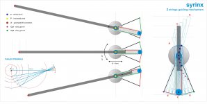
Hi all. Impressive debate on this arm, thank you for all the helpful contributions. An extensible arm is the most obvious consequence of the Thales triangle, and the driving system is a 1: 1 hoist, used for thousands of years to move objects. But simple things are sometimes like "the purloined letter" by E. A. Poe. Easier to find for a child than a detective.
Some posts made me think that my drawings were not clear, so I did a new one, hope better. Unlike opinions, graphics may be verified: a good advantage for all, author included. (thank you Doug, great work, now waiting for your advice).
I've previously said what was to say about my project, possible advantages and residual doubts: this thread deals with geometries and this I've tried to do, searching solutions for a zero offset, and a proper geometry for skating.
There are still around what Ray defines arm's problems, which maybe do not generate skating technically, but similar issues. I have some ideas where to look, but I'm glad to leave the hunting to experts, better if armed with graphics.
Of course I also have my opinions and my myths: eg. that azimuth is most relevant than the tracking error (just look at the shape of a stylus) eg. vectors breakdown, eg.that getting the needed side force (not too much) from offset is not stupid at all. (post #1241)
So if this arm will sound like a good Baerwald for me will be a great success . As 2wice rightly said, the goal, and pleasure is to experiment, not to make the best arm in the world at home
ciao - carlo
Attachments
I built a rough interpretation of Carlo's very interesting design. The extension mechanism seems to confirm his remarkable drawings.
Would you please perform the string test of diyrayk on it? I bet it would skate.
Dear Alighiszem, let's see if I did the same reasoning: if the arm rotating elongates (1.3mm / degree) it also must be true that elongating it will rotate = skating.
But: the side force generates the torque which then converts rotation into translation with a 4: 1 advantage (ratio between the two levers). The rotation due to the stylus drag would happen inversely, so with a 1: 4 disadvantage.
Data found on web -- stylus drag 0.001 - 0.0005N, to be divided by 4 = 0.025 -- 0.012 gr. not so bad!
dear Doug can you perform the string test with such a light weight? on my old mockup refuses to move even if pulled by a mule!
carlo
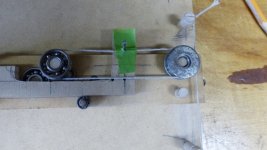
I don't think the arm will skate at all. However, the string and pulleys will produce too much friction. The tighter string is, the more accurate the cartridge position is. Tight string will generate too much friction. It will put too much distress on the cantilever although I have to say it is a clever design.
Carlo,
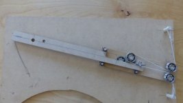
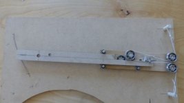
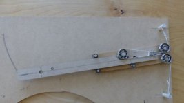
I did the string test. The model rotated and extended very well despite considerable friction. It also "failed." I'll talk more about that in another post.
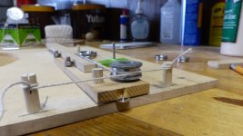
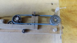
It may be possible to use two bearings instead of three for the extender. I found that moving the string connections behind the rear edge of the bearing helps reduce tension and bearing load.
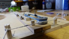
My own concern about string tension and super10018's question led me to the rubber band idea in the second set of photos.
Super10018,
String tension is a concern. I found that the string can be a bit lax without causing problems for the model. Real life? Who knows? I considered a tape or belt and your question prompted me to try the rubber band. It works, but again -real life?
I did the string test. The model rotated and extended very well despite considerable friction. It also "failed." I'll talk more about that in another post.
It may be possible to use two bearings instead of three for the extender. I found that moving the string connections behind the rear edge of the bearing helps reduce tension and bearing load.
My own concern about string tension and super10018's question led me to the rubber band idea in the second set of photos.
Super10018,
String tension is a concern. I found that the string can be a bit lax without causing problems for the model. Real life? Who knows? I considered a tape or belt and your question prompted me to try the rubber band. It works, but again -real life?
Attachments
My model of Carlo's design "failed" the string test as did the other six PLT arms, including a Schroeder clone, I tested.
Although I've argued otherwise, there seems to be a consensus, supported by Frank Schroeder, that the DIY PLTs here skate, but the point, the challenge, of this thread is passive pivoting tangency, not skatelessness, so unless there is a claim that skating indicates tangency failure, I'm not sure I understand why that hobgoblin keeps raising its head.
Pivoting LTs have been designed and built to move to the right and forward simultaneously and continuously when force is applied at the stylus. So when a string is attached to the front and pulled, they move forward and to the right. It's what they are supposed to do. If pulled from the front, they move right. If pushed from the left, they move forward.
Failure, for these arms, is to not do that.
I believe the apparently simple string test is a poor indicator of stylus drag because, like most analogies, it leaves out important details, some of them contradictory. For instance, it's badly out of scale in direction, and magnitude. In addition, it can't address the time factor, and, most importantly, doesn't isolate stylus drag from the other forces working on the arm.
To the extent there are skating problems for PLTs, there are very likely good solutions. Maybe the posters who have thought a lot about the problem could analyze the particulars of PLTs and offer their ideas.
Thank you, DougT. My notion of how to respond to the OP's challenge fails the string test as well but I believe it will play records and reproduce music as well as my very dated references. Hard to believe I promised a submission to this thread back in 2011 (#192) but time flies when old bodies are wrestling with old houses.
FredM
FredM
Hey Fred,
Always good to see a post from you. I understand completely about old bods, houses, and tempus fugiting.
Does your "notion" mean you've built a PLT? Photos would be cool.
Did you have a decent shot at eclipse viewing up there?
Always good to see a post from you. I understand completely about old bods, houses, and tempus fugiting.
Does your "notion" mean you've built a PLT? Photos would be cool.
Did you have a decent shot at eclipse viewing up there?
Last edited:
100% Perfection can not be achieved. If we give weightage to tangential tracking advantage, small skating force is a good compromise. As whatever skating force it shows it will be very low compared to pivoted offset tonearms.
nocdplz's designs are fantastic. With little animation we can see actual working and feel of the working. Tonearm can be made light weight and pivots can be extremely low friction material and one is good to go. Isn't it ? After all some pivoted tonearm designs avoid antiskating altogether.
Regards
nocdplz's designs are fantastic. With little animation we can see actual working and feel of the working. Tonearm can be made light weight and pivots can be extremely low friction material and one is good to go. Isn't it ? After all some pivoted tonearm designs avoid antiskating altogether.
Regards
Hi all - great work: That's the right way to go, many heads work better than just one, especially mine.
To cook my arm was used a good recipe (pivot and forces aligned to the cantilever etc) but then the post # 1398 of Alighiszem made me think, because he knows well what he says, and even if the mockup gave me no answers, finally realized that pulling the stylus the system becomes reversible.
Any driving system has to rotate the arm (even mine that seems to perform only the elongation) so the force exerted has anyway a side component that can induce skating.
The problem is to understand how much. I made a reassuring hypothesis, but for example Niffy's results give the same skate of baerwald. It would be useful to go deeper.
Doug: First of all thanks, clever diying: the idea of 2 pulleys + belt is really clever: one pulley less and the others now working with a better load - and a bit of protection for cartridge as bonus. The only problem is that it needs larger pulleys. Same opinion about string test, a clever, fantastic approach, but not completely exaustive.
Super 10018 - What you say is my first concern (i've compared to a heavy dampening), partly reassured by the mockup, where there is no need for a great tension. You can see a 0.8 - 1 mm piano wire used in the plan for the hooking points
Hiten - sometimes two bearings are better than one, especially with small ones with just one set of balls that cannot afford offset loads the right way. Less play, less chattering, just a bit more friction . Thanks for appreciation, it's easy for me to put together puzzles with parts of previous realizations
carlo
Last edited:
- Home
- Source & Line
- Analogue Source
- Angling for 90° - tangential pivot tonearms