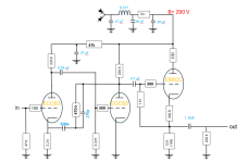
I have added the cathode stage but there is a severe problem with a popping sound coming once every second. I will try to find the cause of that before any further work
Probably a low frequency oscillation through the power supply.
Increase the supply capacitance values, and/or add supply decoupling between the first and second stages.
In a bad case, also reduce the value of the coupling capacitors between the first and second stages.
Increase the supply capacitance values, and/or add supply decoupling between the first and second stages.
In a bad case, also reduce the value of the coupling capacitors between the first and second stages.
I have been reading on valvewizards homepage and made some changes, specially to the buffer stage (like grid stopper and moving the output capacitor), se below. I have now included the power supply in the schematic.

It works, but only when one channel is driven. When I try using both channels the sound commes and goes. No popping or anything. Just the sound that should be there but pulsating in volume with a resonanse at about 2-3 Hz or so (give or take).
It works, but only when one channel is driven. When I try using both channels the sound commes and goes. No popping or anything. Just the sound that should be there but pulsating in volume with a resonanse at about 2-3 Hz or so (give or take).
Your output coupling cap is grounded at the output by the volume potentiometer? You have it wired correctly?
I would also de-couple the two amplification stages, as EJP already suggested. Since the input stage only requires something like 0.5mA, you can use a fairly high value resistor (at least 47k Ohm) here to get the PSU noise down for the input stage as well. You will need another capacitor after it.
I didn't have that in the simulations I posted earlier, but of course I do that too. I am using a linear voltage regulator (LR8) instead of an RC network just because I love the added complexity. 😉
Last edited:
You need a grid stopper on V2, and/or decoupling to V1 plate. But I still don’t know why you have all this gain. That’s part of the problem.
How much grid stop? I hade suggestions of 100 ohms and 390 k ohms in this thred. Big difference. For the buffer stage I used 1k ohms as it was what valvewizard used.You need a grid stopper on V2, and/or decoupling to V1 plate. But I still don’t know why you have all this gain. That’s part of the problem.
Move the power supply decoupling to between the first and second stages, instead of between the second and third stages.
If that is not enough, also reduce the first coupling capacitor from 0.02uF to around 0.005uF.
If that is not enough, also reduce the first coupling capacitor from 0.02uF to around 0.005uF.
A grid stopper only needs to be between 100 and 1k Ohms. For small input signals, I use 100 ohms. When driving the grid of an output tube, I use 1k Ohms.
For the grid of V2 I would suggest around 300 ohms. 270 Ohms would be perfectly fine. The same goes for the grid stopper on V3.
For the grid of V2 I would suggest around 300 ohms. 270 Ohms would be perfectly fine. The same goes for the grid stopper on V3.

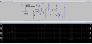
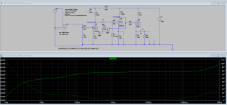
Here, I took your schematic version and made the adjustments, as it more ideally should look (imho). The frequency response for the above simulated well.
If you add the 2k2 cathode resistor to V2, then you will need to by-pass it with a 100uF capacitor (10v or so is fine), or you will not get the bass response you are looking for.
Check these LTspice simulations to understand.


Ian
Last edited:
A ksc3503 will also work as the buffer if there is no extra heater power or room for another tube in the chassis.
- Home
- Amplifiers
- Tubes / Valves
- Angelfire phone preamp - no bass