

I was thinking a tube buffer like this. Will it work?
Direct coupling of the CF is ok, and is used often, even way back in the Marantz 7C and Audio Research SP-3A.
Hi to all,
Following schematic actually designed by Thorsten Loesch worked like a charm for me.
https://www.diyaudio.com/community/threads/tube-phono-stage.92167/
Regards,
George
Following schematic actually designed by Thorsten Loesch worked like a charm for me.
https://www.diyaudio.com/community/threads/tube-phono-stage.92167/
Regards,
George
I was thinking a tube buffer like this. Will it work?
A tube buffer is not as good as a MOSFET, but yes, it will work.
My advice:
1. Output coupling cap should ideally be 1uF instead of 0.1uF (as a minimum, I would suggest 0.47uF).
2. Carefully measure the RIAA caps and resistors. Use more than one cap in parallel to get correct values if needed.
3. I would use the RIAA values as shown in my simulation because I trust my SPICE models. They most closely matched my measured values in real life. But hey, results may vary so this is entirely up to you.
4. Use grid stoppers. Also ferrite beads might help to get rid of any RF hash.
5. 12ax7's don't make particularly good cathode followers. To help things, at least run with a little more current. Each 12ax7 triode can dissipate up to 1W, so having it dissipate 0.33W is not going to be am. I don't know your power supply, but it can surely spare an extra 1 mA. Check to be certain.
6. You could also use a 12au7 on the cathode follower. They're cheaper and you won't hear any difference.
Check the attachment. It's not quite the same as Tim Paravacini's but hey...
Attachments
Last edited:
This is the plan:

As for the RIAA equalisation part (330k & 200 pf), I will adress that later if I get the preamp working.
As for the RIAA equalisation part (330k & 200 pf), I will adress that later if I get the preamp working.
Aside from the heater circuit, what's missing? If you are referring to the absence of a cathode resistor in the second stage, note that this stage is grid leak biased by the large 3.3M grid leak resistor. So that is not an oversight; it was a feature of the original design. I personally wouldn't do this, but it should work in this circuit because the stage only needs a small amount of negative bias for the 12AX7 since the audio signal levels are in the millivolt range.
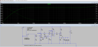
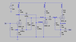
I finally got around to modeling this circuit, which comes with some caveats. Most vacuum tube SPICE models don't account for grid current but that is a must in a circuit which uses grid leak bias like this one. Adrian Immler's tube (valve) models are among the best in this respect so I used those for simulation (hence the "AI" suffix on the model names). Attached is the schematic with DC currents and voltages shown. These all pass the "sanity test" and suggest that all three stages will at least bias up to workable operating points.
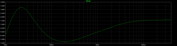
But the RIAA accuracy is very poor (see attached plot). The RIAA standard has three time constants and I couldn't see how the feedback components (along with C2) could get you there. So if accurate RIAA playback is an objective there are a lot better circuits to build from. The one referred to in post #23 is a similar design and worth considering. Although I didn't model that one, its passive RIAA filter is at least topologically correct. Adding an output buffer (tube or MOSFET) would be a straightforward modification.
But the RIAA accuracy is very poor (see attached plot). The RIAA standard has three time constants and I couldn't see how the feedback components (along with C2) could get you there. So if accurate RIAA playback is an objective there are a lot better circuits to build from. The one referred to in post #23 is a similar design and worth considering. Although I didn't model that one, its passive RIAA filter is at least topologically correct. Adding an output buffer (tube or MOSFET) would be a straightforward modification.
Attachments
Last edited:
I know that the RIAA accuracy is bad. Soulmerchant has suggested changes to the circuit that will adress that and I intend to imply them if this cathode follower stage works like intended.
If the cathode stage does not fix the overall bigger problem with horrible (not just bad) RIAA accuracy, I will have to think about bigger changes. Probably other designs, like the one in post 23, EAR 834P or something else.
If the cathode stage does not fix the overall bigger problem with horrible (not just bad) RIAA accuracy, I will have to think about bigger changes. Probably other designs, like the one in post 23, EAR 834P or something else.
The open loop gain must be exactly 20dB higher than the desired midband RIAA gain.
For example, if you want mid-band RIAA gain of 40dB, the open loop gain must be 60dB.
That's how the 3180uS time constant will be approximated.
The EAR is similar to this circuit and uses the same principle, except where the feedback goes.
In this circuit, the feedback includes two gain stages, but the EAR feedback only includes one gain stage.
Adding a cathode follower (or MOSFET buffer) to the output is not going to fix the RIAA errors, which are caused by the feedback network. Although the suggested changes do smooth out the curve, increasing the 330k feedback resistor value also increases the mid-band gain because that change reduces the feedback ratio. I would be inclined to start with a design that doesn't require a lot of modifications to make it perform acceptably. There are plenty of phono preamp circuits posted in these forums.If the cathode stage does not fix the overall bigger problem with horrible (not just bad) RIAA accuracy, I will have to think about bigger changes. Probably other designs, like the one in post 23, EAR 834P or something else.
I am aware that the buffer stage will not fix the RIAA errors. But at this stage there are bigger problems that has to be addressed first.Adding a cathode follower (or MOSFET buffer) to the output is not going to fix the RIAA errors, which are caused by the feedback network. Although the suggested changes do smooth out the curve, increasing the 330k feedback resistor value also increases the mid-band gain because that change reduces the feedback ratio. I would be inclined to start with a design that doesn't require a lot of modifications to make it perform acceptably. There are plenty of phono preamp circuits posted in these forums.
But changing the feedback resistor from 330k to 470k is quite easy so I might just as well do that now if it helps with the RIAA linearity.
Increasing the 330k resistor to 470k will increase the mid-band gain to about x240, or 47 dB. That's quite high for a moving-magnet phono preamp. But if you are OK with that then you might have your solution.
With that observation, I'm bowing out of the conversation. Good luck.
With that observation, I'm bowing out of the conversation. Good luck.
Last edited:
- Home
- Amplifiers
- Tubes / Valves
- Angelfire phone preamp - no bass