Hello everyone
I've built a Angelfire phono amp (the second one) but it has no bass output. The cartridge is a Shure M44-7. It is a passive preamp with a phono stage. The other two inputs works great. The phono input has ample gain and no hum but it is very very bright sounding and lacks all bass output.

I've checked that all the components are correct, and they seem to be.


Any guesses? The tubes are JJ ecc83S
Best regards
I've built a Angelfire phono amp (the second one) but it has no bass output. The cartridge is a Shure M44-7. It is a passive preamp with a phono stage. The other two inputs works great. The phono input has ample gain and no hum but it is very very bright sounding and lacks all bass output.
I've checked that all the components are correct, and they seem to be.
Any guesses? The tubes are JJ ecc83S
Best regards
Have you actually checked the equalized frequency response? The brightness may just be LF deviation from RIAA.
A topology like this is very difficult to design with both flat low frequency response and normal (34 - 40 dB) gain.
This circuit operates open loop at low frequencies, so the output bass level depends directly on the gain of the tubes.
If you measure the open loop gain (with RIAA disconnected), then the 1kHz gain with RIAA must be 1/10 (-20dB)
relative to that gain. If it is not, then the overall bass level will be higher or lower than the correct level.
I did not design the topology, it's a link i found online from a site called angelfire, link is here: https://www.angelfire.com/electronic/funwithtubes/Amp-Phono.html
it is the second schematic
it is the second schematic
First thing - it's not the tubes.
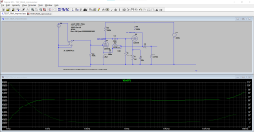
I just ran your chosen circuit in LT-Spice and the frequency response isn't really anything I would suggest is accurate for RIAA.
Maybe it can be fixed, but if you are going for active RIAA correction, you need to really get the right components and make sure they measure accurately. I do active RIAA and passive RIAA. I find active sounds 'livelier' but building a proven passive RIAA correction is a FAR wiser decision if you haven't build one before.
Anyhow, I attached the schematic as I ran it in LT-Spice. Maybe I missed something but I think it is correct. You want to see a nice flat frequency response on this simulation.
Attachments

Last edited:

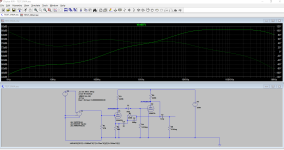
Here, these changes in the attached schematic might work better. I offer no garantees though! This is just a quick simulation.
Use a 2k2 cathode resistor on the second triode, and by-pass it with 100uF (10v) cap.
Then change the resistor and cap values in the RIAA network to values I put into my LT Spice. You will probably need to trim some values.
It could be that in your original RIAA that some value is incorrect (or something is shorted) too. I would not rule that out.
Attachments
That preamp can only drive 200k ohm loads without a buffer. What in the next stage input impedance ?
@soulmerchant thank you for the simulations. The sound is more like not having an RIAA-equalization at all, and the difference is much more than in your simulations. But if i get it to sound somewhat accurate i will try your modifications.
@stocktrader200 it is coupled to a volume pot, 100k, then to a 6SL7 tube.
@stocktrader200 it is coupled to a volume pot, 100k, then to a 6SL7 tube.
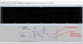
That preamp can only drive 200k ohm loads without a buffer. What in the next stage input impedance ?
That's an excellent observation. I see the OP answered and says its a 100k volume pot. But what if the input impedance of the next stage is only 10k Ohm?
See the attached simulation.
Attachments
Last edited:
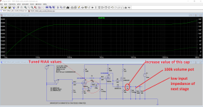
Ideally speaking, this phono amp should have no volume control, and the following pre-amp would then have the 100k Ohm volume control (by-passed by a 1Meg resistor for safety).
If this amp had an output buffer stage, it could better support a volume control. I am using MOSFET followers for output buffers on phono amps. They take up very little space.
If this amp had an output buffer stage, it could better support a volume control. I am using MOSFET followers for output buffers on phono amps. They take up very little space.
Last edited:
The measured curve will be considerably changed in the bass by additional loading of the output, even 500k.
Thank you all for the support. Anyone got any schematic for a suitable tube buffer? Preferably with E88CC/6922 as I've got some. And they are useful in many builds. I should be able to squeeze one more tube in the same box without too much hassle.
The power supply will need to be able to power a buffer per channel.
Since 12AX7 tubes use little current, the supply is likely to need redesign to supply the buffer current.
Since 12AX7 tubes use little current, the supply is likely to need redesign to supply the buffer current.
Rayma is right. I am using a MOSFET follower usually because it performs extremely well, and no additional heater current is required with a MOSFET. It also doesn't take up much space. Make sure your B+ can deliver the (modest) extra current for the buffer. Btw - nobody can hear the difference between MOSFET follower and tube cathode follower either. 😉
I would suggest you try zvn0545a (and protect the gate with a Zener diode). Just don't exceed it's 700mW limit. This device works well with the 12ax7 due to its very low reverse transfer capacitance value.
Anyhow, check the attachment to see what this might look like. I made a few additional suggestions in the attachment too. If you implement a buffer, then use a decent sized coupling cap, then you will get far better performance.
Attachments
Last edited:
btw - nice turntable, but the TD135 is prone to rumble. Once you get that bass signal you will probably discover this.
For a similar vintage turntable that doesn't rumble, check out Lenco L70 or L75...
For a similar vintage turntable that doesn't rumble, check out Lenco L70 or L75...
That's a nice device, but my "go to" TO-92 MOSFET for buffer duty is the STmicroelectronics STQ2HNK60ZR-AP. It is rated at 600V and 3W, and has built-in Zener diode protection. It's also a little cheaper as of this writing.I would suggest you try zvn0545a (and protect the gate with a Zener diode).
The STQ2HNK60ZR-AP has a Crss of 7pF Crss while the zvn0545a has a Crss value of 4pF.
But it could be good! There are many new devices these days to consider. Check out the STQ2LN60K3-AP (for example) 😉
But it could be good! There are many new devices these days to consider. Check out the STQ2LN60K3-AP (for example) 😉
I noticed the 3 pF difference in reverse transfer capacitance but decided (for myself) that this difference was insignificant in an audio frequency buffer application. I like the higher voltage and dissipation ratings, and the fact that no external Zener diodes are required. But I was simply offering the OP an alternative MOSFET that has worked well for me.
I think that the power supply can take the extra load. It is strong enough for a small SET amp, but I will dubble check so the filament current is not too much as it is DC converted.
@soulmerchant the TD135 i nice. Looks real cool. A poor mans TD124. I mainly use it on my primary system but it has been going through som TLC in the hobby-room, changing some of the rubber dampers, the belt and the "disc". It runs real quiet. Hence I thought i would try it with the new RIAA.
@soulmerchant the TD135 i nice. Looks real cool. A poor mans TD124. I mainly use it on my primary system but it has been going through som TLC in the hobby-room, changing some of the rubber dampers, the belt and the "disc". It runs real quiet. Hence I thought i would try it with the new RIAA.
- Home
- Amplifiers
- Tubes / Valves
- Angelfire phone preamp - no bass