Has anyone considered designing and building an FM tuner? From an audiophile standpoint there is probably little to be gained thereby. In the USA, at least, with few exceptions, both the audio and aesthetic quality of broadcast FM material leave much to be desired. However, as an educational project it might be worthwhile.
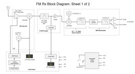
This design has, for the most part, been coded and verified in ADS and later in LTSPICE. The front end is a conventional 4-stage low gain tuned amplifier; low gain was chosen to avoid high level input overload and to avoid the need for AGC. The LO is a Vackar design and is buffered via a high speed comparator for isolation purposes. Down conversion to 10.7 MHz is implemented with a Mini Circuits DB mixer. Both the RF and LO stages utilize varactor tuning, where the tuning voltage is sourced via a precision 10.00V reference and is shifted/scaled to allow the RF amp and LO to track over 88.1-108.1 MHz and 77.4-97.4 MHz, respectively.
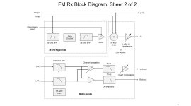
Demodulation is based upon a double conversion scheme, where the first down-convert is to 10.7 MHz and utilizes ceramic FM filters. The second down conversion to 1.0 MHz permits a low noise, low distortion delay line based demodulation to baseband. 1.0 MHz was chosen because it permits the use of easily implementable digital delay, and the carrier frequency is sufficiently high that recovery of BB signals requires only simple L/C filters. Subsequent stages regenerate a 38 kHz chopping frequency from the 19 kHz pilot tone and perform the filtering/matrixing to recover the L and R channels from the L+R signal. The front end sections have been built and tested, although I plan a redesign to implement some improvements.
This design has, for the most part, been coded and verified in ADS and later in LTSPICE. The front end is a conventional 4-stage low gain tuned amplifier; low gain was chosen to avoid high level input overload and to avoid the need for AGC. The LO is a Vackar design and is buffered via a high speed comparator for isolation purposes. Down conversion to 10.7 MHz is implemented with a Mini Circuits DB mixer. Both the RF and LO stages utilize varactor tuning, where the tuning voltage is sourced via a precision 10.00V reference and is shifted/scaled to allow the RF amp and LO to track over 88.1-108.1 MHz and 77.4-97.4 MHz, respectively.
Demodulation is based upon a double conversion scheme, where the first down-convert is to 10.7 MHz and utilizes ceramic FM filters. The second down conversion to 1.0 MHz permits a low noise, low distortion delay line based demodulation to baseband. 1.0 MHz was chosen because it permits the use of easily implementable digital delay, and the carrier frequency is sufficiently high that recovery of BB signals requires only simple L/C filters. Subsequent stages regenerate a 38 kHz chopping frequency from the 19 kHz pilot tone and perform the filtering/matrixing to recover the L and R channels from the L+R signal. The front end sections have been built and tested, although I plan a redesign to implement some improvements.
Attachments

I built a fm radio too but it was much easier using a Si4735 chip. Good luck in your efforts. Would like to hear about your tuners performance on signals over the air
What Kay said. All your image frequencies will be from 66.7 to 86.7 MHz which is occupied by analog TV channels 4-6 (think high power and broad band). If you go to high side injection, your image freqs will be mostly aircraft band (low power narrow band).
I don't think ceramic filters for the 1st IF will give you the adjacent channel rejection desirable; crystal filters will have better rejection and better group delay.
I don't think ceramic filters for the 1st IF will give you the adjacent channel rejection desirable; crystal filters will have better rejection and better group delay.
In addition, a LO frequency range of 98.2 to 118.7 Mhz means a ratio of 1/1.21, easier to achieve than a 76,8 to 97.3 MHz range with a ratio of 1/1.27. My calculations are based on a FM range from 87.5 to 108 MHz, as it is usual here.
Best regards!
Best regards!
Looking around, this seems like unobtanium, certainly in the UK. Another route would be SDR (software defined radio).I built a fm radio too but it was much easier using a Si4735 chip.
A while back (sometime around the '70s), I built my FM radio with all discrete circuitry apart from the stereo decoder. Big difference then was that I was in the trade and had access to a professional RF lab.
Last edited:
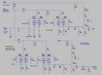
Actually, the components are not that difficult to obtain, at least in the USA, and the circuits are not that difficult to design and build. I searched around for single chip demodulator/matrix chips, but none appear to be available. Therefore I designed the demod/matrix circuits from scratch. Each of the tuner's subsections is housed on a separate PCB; this makes modifications and upgrades more feasible. Attached is the circuit for the RF amp. It has been built and tested. I will post additional subsections as they get designed as well as the names of component suppliers.
Attachments
To give thread a bump with not technical post.
I will not build my own FM tuner, but I still enjoy listening radio.
In Europe we have 2 types of stations worth listening; First usually 3rd program of state radio, dedicated to culture and regularly has some live talks how's, amazing how FM can still bring talking people inside my room. Also lots of good classical music (not only classical) , good actors reading books and essays... Lots of goodies.
Second is "student" radios, not so good in quality but sometimes brings along bucket of new interesting music.
Both types of stations are not commercial, so no adverts.
I still have Sony ST-5000F and Yamaha CT 1010, classical high-end pieces with 5-gang capacitors.
But third one is might be most interesting and might be sounding even the best; British Qed T231, it is small understated machine with Larsholf FM module. I googled and Larsholf seems out of business, but sound of their tuner is great and I believe it was mass produced years ago, so could be available for cheap as s/h or as part of some unit.
Might be easier way to practice is to refurbish one of these, now cheap, classics and/or to use ready tuner module (that can always be opened and studied). New generations like quicker way to result, building own FM tuner might be long way and w/o much future, FM is dying, slowly but still doomed
Regarding refurbishing vs. building: I already own a perfectly functional FM tuner, a Marantz 120, which I refurbished last year. The purpose of designing and building a tuner from scratch has nothing to do with cost or the time involved in building. Rather it is a opportunity for learning. Most of my career as an electronics engineer (I'm now retired) was spent designing digital stuff including writing the Phy layer specifications for USB 1.0 and PCIe 2.0, 3.0 and 4.0. One of my last assignments was designing a multi Gb/s data link that operated over a dielectric waveguide. Such a waveguide has a low freq cutoff and needs to operate via carrier modulation. This experience piqued my interest in learning about RF, and designing an FM tuner seems like a good undertaking to that end.
Jeff
Jeff
My FM receiver is under construction, the tuner (pic below) works well and has been canned. The IF was double superhet also but I'll change the 2nd IF from 340 KHz to 1600 Khz after a sim showed that a PLL at 1600 KHz can achieve both low enough distortion and good enough sensitivity.

Yeah, sure. I just wanted to say that FM listening still has merit, and might be going from eased starting point (fm module or rebuilt) could encourage some cause of faster result.The purpose of designing and building a tuner from scratch has nothing to do with cost or the time involved in building. Rather it is a opportunity for learning.
I happend to have some NOS variable inductor and one tuning capacitor. If someone wants them to built tuner at cost of p&p just ask.
Why bother with variable tuning capacitors? I was using varactors back in the 70's along with a phased lock loop oscillator to do my FM tuner back then. It worked great!
Nowadays even SDR can be fitted with varactor diodes, to provide higher sensitivity without broadband overload. However local stations still can cause overloading, preventing weak station reception on nearby channels. No such issues with variable tuning caps. The pics are self-explanatory (look at the overload indicator and tuning freq.


The design I am considering does indeed utilize varactor diodes. Here is the schematic for the front end RF amplifier stage. The only adjustments required for alignment are the 4 variable inductors. Gain is purposely set low at approx. 6 dB in order to avoid overload in the presence of strong signals. Attached is a plot of the front end selectivity. Most of the gain is provided by the IF and limiter sections, and per-channel selectivity is provided by a 4 or 6-stage (user selectable) ceramic filter IF stage.
Attachments

i built an FM tuner in the 70th as well. Gifted with hi-res ears at that time I discovered that 10,7MHz ceramic filters were a no-go.
Due to non-linear group delay there was audible distortion in the presence region that sounded like detuned reception.
You could not find the smooth sounding mid-point no matter were tuned the knob.
Really annoying. It took me some investigation to locate the elephant in the room.
I swapped from ceramic to inductive 5-pole if filter blocks from Toko that were tuned to linear group delay.
This did the trick.
Some ceramic filters are better than others in that sense. At least Murata used to have 10.7 MHz ceramic filters that were designed for a more or less flat group delay, besides the standard models that were not.
I have a bunch of Murata filters that have a reasonably flat GD response. However, it should be possible to construct L/C filters with better characteristics. The main problem is the sheer complexity of such circuits, not to mention the task of aligning them. Since both amplitude and phase (GD) must be measured it is likely that a VNA is required,
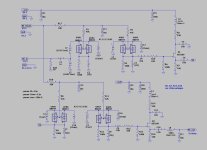
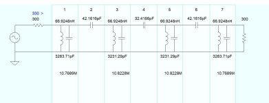
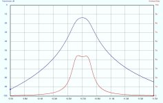
Attached is an example of a 4th order L/C filter. It has a passband of 150 kHz and good GD over that range. However, to match the selectivity of the ceramic filter IF stage would require up to six of these stages.
Attached is an example of a 4th order L/C filter. It has a passband of 150 kHz and good GD over that range. However, to match the selectivity of the ceramic filter IF stage would require up to six of these stages.
Attachments
- Home
- Source & Line
- Analogue Source
- And Now for Something Completely Different