At that time i used 4 of these 5-pole filter blocks with if-stages in between. Selectivity was ok but not that sharp compared to ceramic filters - but the sound was fine.
Back in 1968, they usually tuned one tank at a time to the centre frequency with the other tanks shorted, or at least that's what I understood from the bandpass filter section in Zverev's Handbook of Filter Synthesis, https://archive.org/details/HandbookOfFilterSynthesis You need a grid dipper then.

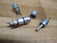
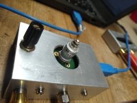
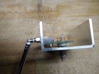
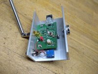
At the end you have to wobble to verify linearity. I did this using a free varactor tuner and modulating the control-voltage with some audio ac voltage. Together with a scope x/y plot the transfer curve could be seen. And this looked quite edgy with my Murata SFW 10.7 filters. Meanwhile I designed a test oscillator using actual standard smd parts. The tuning coil is based on a nylon srew giving best stability to fix the windings.
Attachments
Bizarrely I have a copy of this book bought before the days of the Internet ! I have never heard of it since until today !Zverev's Handbook of Filter Synthesis
"wobble" This was the basis of the sweep alignment used up through the Sound Technology 1000A era. It was very much a visual judgment call, and often did more damage than good. Shortly afterwards, the undercoupled Richard Modaferri designs of the McIntosh MR77 and MR78 allowed peak tuning with a distortion analyzer, bumping signal down and simply peaking for least distortion + noise. Just like how front ends are done.
I would definitely not recommend anyone tamper with Modaferri IF filters unless absolutely sure that previous tampering has happened. If you're really a hot shot with hot shot machinery you can and will ignore me anyway, but for mere mortals and working tuners, beware brother beware. Otherwise, peak tune the front end, DC center the discriminator, tune the discriminator secondary for minimum distortion, and check that the MPX works. Done. IMO, of course.
All good fortune,
Chris
There is a hardcopy of Zverev's book at the place where I work, together with a few hundreds of other books about electronics engineering. Of those books, Zverev's is the only one I ever use.
Well that's two then ! I might eBay mine one day, I earned a lot of money from it years ago.There is a hardcopy of Zverev's book at the place where I work,
I also used the Zverev book! Good memories.
I rebuilt the IF of my Marantz tuner, replaced the Murata ceramic filters with Toko 178BBR-3132A Six-pole Linear Phase LC Filters in two stages. But I had to insert an amplifier stage in front and a buffer after each filter. So it went to a separate PCB.
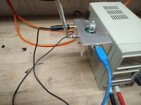
I also built this MPX generator for testing, it works great:
https://pira.cz/eng/stk2en.htm
I rebuilt the IF of my Marantz tuner, replaced the Murata ceramic filters with Toko 178BBR-3132A Six-pole Linear Phase LC Filters in two stages. But I had to insert an amplifier stage in front and a buffer after each filter. So it went to a separate PCB.
I also built this MPX generator for testing, it works great:
https://pira.cz/eng/stk2en.htm
What is the problem with varactors (we call them varicap diodes)?
They change capacity with voltage, that is fine as long as there is only DC voltage on them. But since there is some accompanied RF signal, that signal also modulates the capacitance of the varactor. It wiil cause nonlinear distortion. Keeping the RF signal level very low could help somewhat, but the perfect solution is a multigang variable capacitor, or tuned inductors as used to use in car radios. The latter for less vibration sensitivity.
They change capacity with voltage, that is fine as long as there is only DC voltage on them. But since there is some accompanied RF signal, that signal also modulates the capacitance of the varactor. It wiil cause nonlinear distortion. Keeping the RF signal level very low could help somewhat, but the perfect solution is a multigang variable capacitor, or tuned inductors as used to use in car radios. The latter for less vibration sensitivity.
A less well-known filter book I can highly recommend is DeVerl S. Humpherys, The Analysis, Design, and Synthesis of Electrical Filters, Prentice-Hall, 1970. I borrow it from the Delft university library when I really have to go into the details of filter synthesis.
Back then, Anatol I. Zverev's handbook of filter synthesis was a must and I still have the book. But it was quite a relief when simulators became available. So that in the event of stronger "local" stations (the present ones are 35 Km away, but in line of sight) I could design a wideband tuner, 87 - 108 MHz input filter, VAY1 (0.5W LO) DBM, varactor controlled LO, 60 MHz first IF system with NF still below 7 dB.
Not sure what they did with car audio to get the sensitivity down to 8 dBf, but noticed the other day on a classic Pioneer that it was something like 10.8, and don't recall ever seeing a vintage receiver with better sensitivity than that.
The 50 ohm source impedance is meant to replicate the standard 50 ohms of an RF generator or an antenna driving coax.Why do you put a 50 ohm noise source straight across the input?
Not sure what they did with car audio to get the sensitivity down to 8 dBf, but noticed the other day on a classic Pioneer that it was something like 10.8, and don't recall ever seeing a vintage receiver with better sensitivity than that.
Modern car radios use lots of weak signal processing tricks. To name two that have been in use for a very long time: adaptive IF filter bandwidth and reducing audio bandwidth (high cut) when the signal is weak. (At higher levels, the switching from mono to stereo is done gradually rather than abruptly, so you don't hear a sudden jump in audio noise, but rather a channel separation that gradually increases with the RF signal level.)
These were already in use when the IF signal processing was still analogue. Nowadays it is often digital and there are many other weak signal processing algorithms in use, but I don't know the details of those.
Last edited:
The 50 ohm source impedance is meant to replicate the standard 50 ohms of an RF generator or an antenna driving coax.
I meant R10 in the schematic of post #16. If it models the impedance of the signal generator, it's at a different place in the schematic hierarchy than I would expect. As a result, I mistook it for a part of the RF amplifier.
FM receiving antennas and antenna cables traditionally have 75 ohm or 300 ohm nominal impedances, although 50 ohm is getting more usual (for active car radio antennas anyway). FM transmitting antennas and cables have been 50 ohm for as long as I can remember.
Last edited:
MarcelvdG,
Regarding R10 on the schematic: it is there to serve as a termination to match the impedance of 50 Ohm coax. Termination impedance mismatch can lead to reflections that mimic multipath distortion. I plan on building a Yagi type FM antenna, and it will require a substantial length of coax to connect to the tuner. Why 50 rather than 75 Ohms? Because I have lots of 50 Ohm coax on hand and can design the antenna to match that impedance.
Regarding R10 on the schematic: it is there to serve as a termination to match the impedance of 50 Ohm coax. Termination impedance mismatch can lead to reflections that mimic multipath distortion. I plan on building a Yagi type FM antenna, and it will require a substantial length of coax to connect to the tuner. Why 50 rather than 75 Ohms? Because I have lots of 50 Ohm coax on hand and can design the antenna to match that impedance.
I think that the mis-communication is that RF transmission lines are not (usually) terminated in a lossy resistor, but rather into the active amplifier stage(s) as best as possible (for best power, and thus noise, match), making the resistor a simple (parasitic) liability. Perhaps you mean something different, but the schematic is ambiguous at best.
50 Ohm is standard for measurement gear and 75 Ohm is standard for consumer gear because it scales to 300 Ohm with bifilar transformers and ribbon dipole antennae. Both grandfathered in. There's probably a very interesting story about how 50 Ohms has so many offspring.
All good fortune,
Chris
And 1/4 wavelength poles sticking out of the backyard, sitting on a wine bottle, with copper wire buried in the ground in a radial pattern (72 Ohms). My childhood with a truly great engineer, my father. His friend took a few sections of rain guttering off the house, leaned against the swingset, and shot Fourth of July rockets (mostly) over the backyard neighbors into the abandoned apple orchard beyond. Not all of them acheived escape velocity. We kids had running BB gun battles in those trees - it's a miracle we all came out sighted.
Last edited:
For me it's not at all clear that the reflections you get in the antenna transmission line when both the antenna and the radio have a poor power match can be bad enough to cause a substantial change in transfer over an FM channel, which is only 256 kHz wide for FM stereo, according to Carson's rule. However, assuming that a power match is needed:
Noise matching and power matching are actually not necessarily the same, but otherwise I agree with Chris. You can either try to power match the input to the amplifier stage and hope the noise is not too suboptimal, or use feedback techniques to adjust the input impedance (W. S. Percival, 1939). In either case, you probably get less of a noise penalty than with a termination resistor across the input.
Noise matching and power matching are actually not necessarily the same, but otherwise I agree with Chris. You can either try to power match the input to the amplifier stage and hope the noise is not too suboptimal, or use feedback techniques to adjust the input impedance (W. S. Percival, 1939). In either case, you probably get less of a noise penalty than with a termination resistor across the input.
The op can apply something like this for the FM band:
---
Methodology for Simultaneous Noise and Impedance Matching inW-Band LNAs
---
https://www.eecg.utoronto.ca/~sorinv/papers/sean_nicolson_csics_06_proceedings_paper.pdf
At https://www.pa3fwm.nl/technotes/tn36-zwischenbasis.html
look up the entry for "basis emitter feedback" and "passive augmentation".
---
Methodology for Simultaneous Noise and Impedance Matching inW-Band LNAs
---
https://www.eecg.utoronto.ca/~sorinv/papers/sean_nicolson_csics_06_proceedings_paper.pdf
At https://www.pa3fwm.nl/technotes/tn36-zwischenbasis.html
look up the entry for "basis emitter feedback" and "passive augmentation".
- Home
- Source & Line
- Analogue Source
- And Now for Something Completely Different