As the topic of Class-AC output sparked my interest in the VAS transistor thread, I did some cursory searching and now I'm pretty much sold on the idea.
I did note that much of the information regarding the underlapped AB version of the 'AC' idea was slewed towards using tubes; though this is not really what I wanted to do.
A question that's popped up for me is how can I determine the reactive power levels that the outputs will experience in loaded conditions? It's a little bit different to your typical equal-current multiple OPS stage, as the transistors take different amounts of loading.
I can analyse it easy enough in DC but that doesn't tell me much about what sort of reactive SOA I need to bargain in for either the power pair or the booster pair of transistors.
A second question would be what sort of thermal compensation regime would you employ? The way I see it, as long as you keep the power pair under thermal stability then the boosters will stay in check with it. Obviously placement of the transistors will also take a part in determining the overall thermal transient response, too.
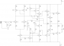
(Note 2SA1708/C4488 shown as drivers - these are much too undersized for the EF-mod ops shown here, my practical choice would be 2SB1167/2SD1724)
I did note that much of the information regarding the underlapped AB version of the 'AC' idea was slewed towards using tubes; though this is not really what I wanted to do.
A question that's popped up for me is how can I determine the reactive power levels that the outputs will experience in loaded conditions? It's a little bit different to your typical equal-current multiple OPS stage, as the transistors take different amounts of loading.
I can analyse it easy enough in DC but that doesn't tell me much about what sort of reactive SOA I need to bargain in for either the power pair or the booster pair of transistors.
A second question would be what sort of thermal compensation regime would you employ? The way I see it, as long as you keep the power pair under thermal stability then the boosters will stay in check with it. Obviously placement of the transistors will also take a part in determining the overall thermal transient response, too.
(Note 2SA1708/C4488 shown as drivers - these are much too undersized for the EF-mod ops shown here, my practical choice would be 2SB1167/2SD1724)
Attachments
Hi
Not that I could help with those somewhat unique problems, the typeface of components is way too small on your schematic to resolve even on my 22" monitor. This is likely going to "disinterest" potential help.
One suggestion...What appears to be an output inclusive feedback connection to the compensation network won't make the task of finding optimum thermal compensation conditions easy, as Mr Self explains. (Linear Audio #0)
So maybe leave out the bells and whistles until a basic, single pole design is functional?
Member
Joined 2009
Paid Member
Hi MT490,
I'm quite interested in a Class AC output structure
I've spent over a year with Class AB and I'm now 'off' that kind of structure. So your thread has my interest. But I'm mostly interested in NO global feedback and perhaps no gain either - how to design a good Class AC power stage buffer would be an excellent starting point which would be a good basis for further work.
I'm afraid my initial investigations using LTSpice didn't produce satisfying results and I'm wondering if it's possible to achieve good results without resorting to the Quad current dumping approach.
Last edited:
Thanks; I have attached here some alternative copies for viewing.Hi
Not that I could help with those somewhat unique problems, the typeface of components is way too small on your schematic to resolve even on my 22" monitor. This is likely going to "disinterest" potential help.
Well I am still only playing around with SPICE at the moment, but leaving it out in practice for analysis is no issue. I'll have to get myself a copy to look at.One suggestion...What appears to be an output inclusive feedback connection to the compensation network won't make the task of finding optimum thermal compensation conditions easy, as Mr Self explains. (Linear Audio #0)
So maybe leave out the bells and whistles until a basic, single pole design is functional?
@Bigun, thanks for your interest 🙂 , although I think what I've shown here is quite far away from a no NFB design; but we can work on that.
I do value simplicity a lot.
Attachments
Thanks; I have attached here some alternative copies for viewing.
Thanks, the thumbnail is fine. I should have said Self was explaining his new compensation scheme; not much more help for you there, though the article is a great write-up to enthuse over! 😎
Past schemes to incorporate class A in B or C class amplifiers seem to have used
A class at very low levels in a bridge arrangement like Quad & Techics as Bigun refers but here, it seems you're attempting to get it to commutate at a much higher power level, akin to class G. It may help to look at that class generally and even Self's G class design, stability and set-up conditions in his standard amplifier text. 'hope you find some insight there. 😕
Last edited:
Indeed this type of Class-AC is a rather wasteful sort, with the idling current being pulled through the full voltage power rails all the time. Additionally the EF stages seem to consume quite a bit of voltage swing (SPICE suggests 33Vpp out of 37+37V)
Sims fairly nicely though. THD-10/FS 0.0039% into 4ohms (0.004x no TMC), with a nice slope downwards for the harmonics. And of course the level decreasing distortion expected from this topology, THD-10/2W-4R 0.00059%
I'm starting to think that the KSC1943 model is broken for temperature simulations, I noticed that the Vbe of this particular transistor doesn't appear to change with temperature in the simulator like the other models.
So far though it seems like this is generally a bad idea for managing the biases, as change of the master bias varies the overlap of the AB2 conduction regions directly. Meaning that if the master Vbe drops due to temperature, the cross point for the AB2 pairs also becomes narrower and narrower..
Member
Joined 2009
Paid Member
Perhaps a better approach maybe to take the path described by Broskie, here: CCDA & Class-AC
The figure labeled "Class AC IMC" is currently the direction I'm looking at.
The figure labeled "Class AC IMC" is currently the direction I'm looking at.
Interesting reference, Broskie's SS class AC. Thanks Bigun. I note he's suggesting Thermaltraks to resolve the thermal compensation issues. I guess that's a reasonable move when the option of designing a fancy integrator control system is not going to be real attractive at prototype level.
Member
Joined 2009
Paid Member
I'm no expert, but I understand the biggest driver for accurate thermal compensation is to control the behaviour of a Class AB output stage so that cross-over distortion is minimized and to avoid dynamic effects where the bias point moves after a burst of high power signals.
For Class A this is not an issue, you just need to avoid thermal runaway. For Class C it may not be a big issue either since some movement of the point where the Class C amp 'kicks-in' should be OK. In other words, I'm not sure you need an accurate thermal servo here if adopting Class A + C.
For Class A this is not an issue, you just need to avoid thermal runaway. For Class C it may not be a big issue either since some movement of the point where the Class C amp 'kicks-in' should be OK. In other words, I'm not sure you need an accurate thermal servo here if adopting Class A + C.
Hello folks,
I also found the class-AC interessting. So I build a small Mosfet-Amplifire with a compound stage.
I called him Bemos 😉
The driver have a quiescent current round about 5mA, the Mosfets are not working. They switch on when the driver 20mA loads. And the driver stop at 20mA, the current does not increase. The rest of the current will assume the Mosfets.
This is a simulation with TL-Spice:
It shows the diffent currents and the takeover.
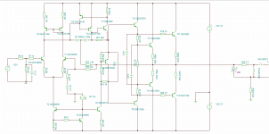
And this is the schematic:
This circuit works and it is very stabil. There are no oscillation. I tested a 1uF condensator parallel to 8ohm and Bemos do not oscillat.
Actually I want to build a class-B amplifire(Bemos), but on closer examination, it is a class-ABC circuit.
What do you think?
I also found the class-AC interessting. So I build a small Mosfet-Amplifire with a compound stage.
I called him Bemos 😉
The driver have a quiescent current round about 5mA, the Mosfets are not working. They switch on when the driver 20mA loads. And the driver stop at 20mA, the current does not increase. The rest of the current will assume the Mosfets.
This is a simulation with TL-Spice:
An externally hosted image should be here but it was not working when we last tested it.
It shows the diffent currents and the takeover.
And this is the schematic:
An externally hosted image should be here but it was not working when we last tested it.
This circuit works and it is very stabil. There are no oscillation. I tested a 1uF condensator parallel to 8ohm and Bemos do not oscillat.
Actually I want to build a class-B amplifire(Bemos), but on closer examination, it is a class-ABC circuit.
What do you think?
Member
Joined 2009
Paid Member
Looks very nice moschfet !
I would be interested to know how well it would work if you allowed more current from the Class A regime, for a Class AC amplifier I'd be wanting to see the switch-over to Class C at a much higher level than 20mA - that's more like Class AB in my books. Not sure if you have enough heatsinking to allow a switchover at 500mA for example which may get us close to 1W into 8Ohm ?
I would be interested to know how well it would work if you allowed more current from the Class A regime, for a Class AC amplifier I'd be wanting to see the switch-over to Class C at a much higher level than 20mA - that's more like Class AB in my books. Not sure if you have enough heatsinking to allow a switchover at 500mA for example which may get us close to 1W into 8Ohm ?
Last edited:
Hi Bigun,
500mA is much to much for this topologie. My experiments with 50mA was to high for the driverstage. It become to hot without a heatsink.
Here is a picture of Bemos:
You can see the driver, Q13 and Q17 / Q14 and Q18 are stick together for the termal kompensation.
I would need a complet new Layout and a new tuning.
I just measure my last circuit, the driver has a quiescent current of only 2.5mA and the whole Amplifire about 22mA!
The advantage of this circuit is, you do not need a large heat sink.
500mA is much to much for this topologie. My experiments with 50mA was to high for the driverstage. It become to hot without a heatsink.
Here is a picture of Bemos:
An externally hosted image should be here but it was not working when we last tested it.
You can see the driver, Q13 and Q17 / Q14 and Q18 are stick together for the termal kompensation.
I would need a complet new Layout and a new tuning.
I just measure my last circuit, the driver has a quiescent current of only 2.5mA and the whole Amplifire about 22mA!
The advantage of this circuit is, you do not need a large heat sink.
Last edited:
From my observations this is true. The conduction overlap of the system when it moves from A to C only occurs at powers above 1W, and the overlap can be larger than something like Self's Class-B without too much detriment to the sound.For Class A this is not an issue, you just need to avoid thermal runaway. For Class C it may not be a big issue either since some movement of the point where the Class C amp 'kicks-in' should be OK. In other words, I'm not sure you need an accurate thermal servo here if adopting Class A + C.
The first application that I had in mind for this topology was with bi-amp or tri-amp speakers, and with reasonable sensitivity drivers 1W class A covers most material (as Broskie mentions in his article)
I this may be unneccesary however, I think by putting compensation where the 39R in the drivers is could be the solution.
For class A I avoid symmetrical amplifiers, so don't worry about idle current. For class C that is strictly complementary it does not exist, so I don't worry about it as well.
And I don't need any servo, since I have a coupling cap between class A and class C stages that eliminates output voltage drift/shift completely.
You are right; overlap is very large: it starts from cut-off region of class C devices, and ends when clipping. That's why class A+C amps sound much better than class AB amps.
Member
Joined 2009
Paid Member
Wavebourn, please post a picture, I don't know what you are describing ?
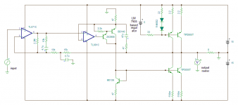
I've attached a simple LTSpice simulation that can be played with, showing Class A, Class AB and Class AC (as per Broskie). They are all symmetrical. When the Class AC version kicks up to Class C the distortion profile is not nice. As far as I can see it's not functioning as it should, i.e. the Class C burners don't alleviate the Class A stage from going into clipping which I believe Broskie had intended with his 'impedance multiplier'. I don't think I've got is configured properly.
p.s. change the file extension from .txt to .asc in order to run this file under LTspice. The forum doesn't recognize the .asc extension (hint to administrators)
Attachments
Yes, your class-ac circuit does not work 🙂
I think you referring to this site:
CCDA & Class-AC
And this circuit is a little bit different.
I think you referring to this site:
CCDA & Class-AC
And this circuit is a little bit different.
Member
Joined 2009
Paid Member
Hi, Wavebourn
I have finishing my simple low power SE ClassA (but not try it yet), how to improve its efficiency? should I switch current source to the ground for negative output, is there another better ways?For class A I avoid symmetrical amplifiers, so don't worry about idle current. For class C that is strictly complementary it does not exist, so I don't worry about it as well.
Attachments
Wavebourn, please post a picture, I don't know what you are describing ?
It is not public domain, sorry. But I revealed key points already.
Broskie's conceptual drawing didn't simulate well either. How would you fix it ?
Yes, you are right. I also can not simulate a well working circuit with Broskies idea.
I would think about class-G... or modify my circuit 😉
- Status
- Not open for further replies.
- Home
- Amplifiers
- Solid State
- Analysing power requirements (Class-A+C/AB2)