Hi,
I have the big VU meter panel from a scrapped Uher Reference No1 power amp (meters were originally driven by the Toshiba TA7318P IC) now I want to use these VU meters with the PeeCeeBee V4H power amp that I am building, I don't want a true VU meter function but just a nice bouncing for visual pleasure, I wonder if this is a suitable driver for my project NEW upgraded edition OF TA7318P VU Meter Driver PCB Board Stereo module | eBay
I have the big VU meter panel from a scrapped Uher Reference No1 power amp (meters were originally driven by the Toshiba TA7318P IC) now I want to use these VU meters with the PeeCeeBee V4H power amp that I am building, I don't want a true VU meter function but just a nice bouncing for visual pleasure, I wonder if this is a suitable driver for my project NEW upgraded edition OF TA7318P VU Meter Driver PCB Board Stereo module | eBay
An externally hosted image should be here but it was not working when we last tested it.
Last edited:
Can you ascertain the sensitivity of the meters ?
It's easy enough to do with a battery and a high(ish) value pot. You'll need a multimeter too.
Simply adjust the pot until the VU meter is at full deflection and read the current on the multimeter.
Typically they are usually only a few mA but this can vary. The battery voltage is unimportant as is the pot, you are only trying to measure the current through the VU meter at full deflection, however do bear in mind that you may only be after a few mA.
Attachments

Last edited:
I see, then I'll try to test the meters later tonight when I am at home and I'll report back, what measurments should I take with the DMM?
Or I can measure the already set values on the original trim pots as I have the whole pcb of the Uher.
Or I can measure the already set values on the original trim pots as I have the whole pcb of the Uher.
Last edited:
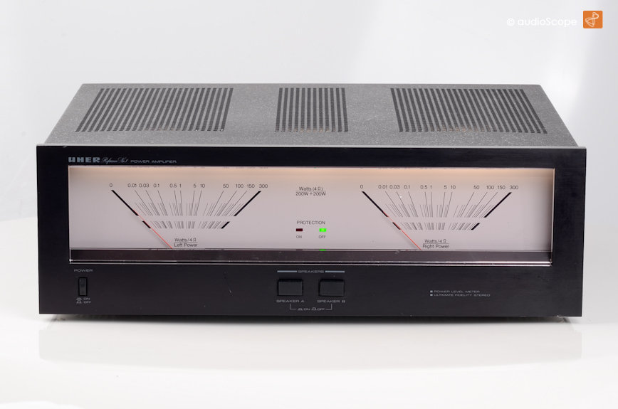
Oooh that looks sooo nice. The unit you linked has pots on its, which I assume is for sensitivity settings. katieandDad might be on to something. These are actualy watt meters, so they are on the output side, VU meters will be on the preamp side, if I remember correctly
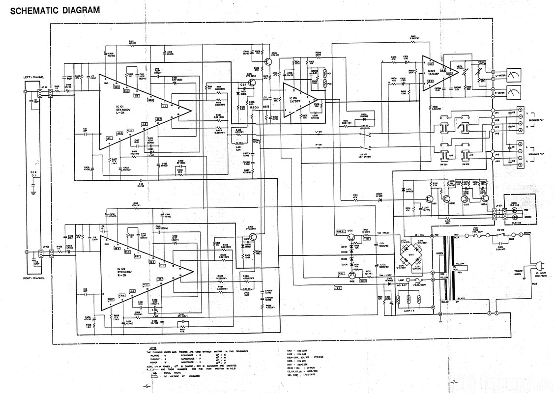
Yes nice looking amp but with crappy sound because of the STKs used, so I scrapped it and kept the meters for the PeeCeeBee V4H project.
Gosh reading through that specs was a nightmare. It shoudl work either way, according to the literature provided
The only problem with a non-VU approach is that we usually listen to our music at quite a modest (surprising low) volume level. 5W RMS is actually reasonably loud.
If you build a circuit to use the meters up to the 300W on their scales, they will hardly move in normal operation.
In order to achieve a decent result you will need an amplifier with a Log characteristic.
If you are intending on driving this circuit with 300W then you will need to pay attention to the attenuation resistors on the input of the driver amplifier.
The part quoted in the OP only has a rating of 3W.
Last edited:
300W into 8 Ohms will need peaks approaching 50V, that would destroy most op-amps without careful attention to attenuation.
To move at normal (very low watts) level, you need a compressor, like in original Uher.
That driver from ebay look suspicious, that IC is not TA7318 (compressor IC). I will not buy that.
TA7318 is SIL9 and that IC is DIL8 and with erased label.
Those four diodes suggest that is only a full wave rectifier and opamp (erased label IC).
Better search for driver with real TA7318.
AGC is not used in the VU or Peak meters.
And here I was going to one that shows 400w in my 27w class A build LOLOL
At MAXIMUM power they would hardly move.
Is the driver board in the original amplifier faulty ?
You could always re-purpose it.
The TA7318P is still available, you could copy the circuit for it.
You could always re-purpose it.
The TA7318P is still available, you could copy the circuit for it.
Do not damage VU meter head - as in old multimeters, turn the diode in parallel in the forward direction. In series 1k resistor?
Проект усилителя. Часть I | Vanolive
Проект усилителя. Часть I | Vanolive
Do not damage VU meter head - as in old multimeters, turn the diode in parallel in the forward direction. In series 1k resistor?
Проект усилителя. Часть I | Vanolive
I mentioned that very early on, these meters are sometimes very sensitive.
Simple # 16 circuits were used in 70s amplifiers and tape recorders. Take measures to protect the heads VU meter from overload and damage.
These circuits typically use 1/4 root which I can't find any leads to.
That is as opposed to 1/2 (square root) algorithms.
x^^0.25 if you are into maths.
That is as opposed to 1/2 (square root) algorithms.
x^^0.25 if you are into maths.
I did find loads of TA7318P ICs on E-Bay, most of them are rescued so you take your chance with them.
- Home
- Amplifiers
- Solid State
- Analog VU meter in power amplifier